Choosing the Best Sheet Metal for Fabrication: A Guide for All Needs
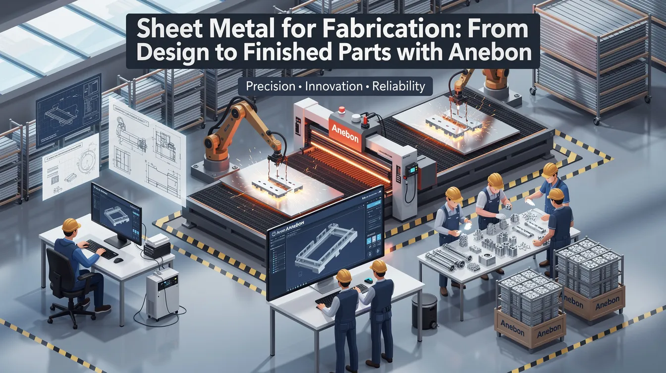
Sheet Metal for Fabrication: From Design to Finished Parts with Anebon
Introduction to Sheet Metal for Fabrication
Sheet metal fabrication is one of the most versatile manufacturing processes in modern industry. It transforms flat metal sheets into functional components through a sequence of operations including cutting, bending, joining, and finishing. Over 50% of car parts are made from sheet metal, and the process is equally vital in aerospace, medical devices, electronics, and industrial machinery. Sheet metal fabrication uses various methods like cutting and bending to produce everything from simple mounting plates to intricate RF shields and enclosures.
Anebon Metal Products Limited has been providing OEM sheet metal and CNC solutions since 2010 from our facility in Dongguan, China. This guide will help engineers and procurement teams choose the right sheet metal for fabrication, select the best processes (laser cutting, press brake forming, deep drawing, sheet metal stamping, and more), and specify the right finishes (powder coating, chromate conversion coating, anodizing) for real-world projects. Sheet metal fabrication allows for high precision and efficiency when material, process, and design are aligned correctly.
Typical Anebon deliverables include brackets, enclosures, bus bars, chassis, RF/EMI shields, and machine covers serving aerospace, medical devices, robotics, and electronics customers worldwide. Whether you need a single prototype or full scale production quantities, understanding the fundamentals covered here will save you time, money, and engineering headaches.
This guide is for:
-
Design engineers specifying sheet metal parts for new products
-
Procurement teams sourcing fabricated metal parts from overseas suppliers
-
R&D teams evaluating materials, tolerances, and finishes during product development
-
Quality and manufacturing engineers working with sheet metal fabricators
What Is Sheet Metal Fabrication?
Sheet metal fabrication is the transformation of flat sheet stock into functional metal parts through cutting, forming, joining, and finishing operations. The raw material arrives as coils or flat sheets from rolling mills, and fabricators like Anebon add value by converting that material into a finished part that meets the customer’s exact dimensional and performance requirements.
The core steps follow a logical order. First comes material sourcing, where the engineer specifies the grade, temper, and material thickness. Next is the cutting process, which profiles the flat workpiece using laser cutting, plasma cutting, waterjet cutting, shearing, or turret punching. Forming follows, where processes like press brake forming, rolling, and deep drawing shape the flat profile into three-dimensional geometry. Joining operations such as mig welding, tig welding, riveting, or hardware insertion assemble multiple pieces. Finally, surface treatment-powder coating, anodizing, chromate conversion coating, plating, or deburring-protects and finishes the part.
It is worth distinguishing between sheet metal manufacturing and sheet metal fabrication. Manufacturing refers to producing the sheet stock itself: rolling ingots into coils, annealing, slitting to width, and cutting to length. Fabrication starts after that stock is purchased. For example, a steel mill cold-rolls a coil to 1.5 mm thickness-that is manufacturing. Anebon then laser-cuts, bends, and welds that 1.5 mm sheet into an electronics enclosure-that is fabrication.
Key sheet metal fabrication operations at a glance:
-
Cutting and blanking (laser, plasma, punch, shear)
-
Forming (press brake, rolling, deep drawing, stamping)
-
Joining (welding, riveting, PEM fastener insertion)
-
Surface finishing (powder coat, anodize, plate, chromate conversion)
Key Sheet Metal Fabrication Processes
Anebon uses a combination of CNC cutting, forming, and secondary operations to achieve tight tolerances on sheet metal parts. On realistic production work, our laser and punch cutting cells hold ±0.05 mm on critical dimensions, and our CNC press brakes deliver consistent bend angles across long production runs. The choice of sheet metal fabrication techniques depends on material type, thickness, part geometry, tolerance requirements, and production volume.
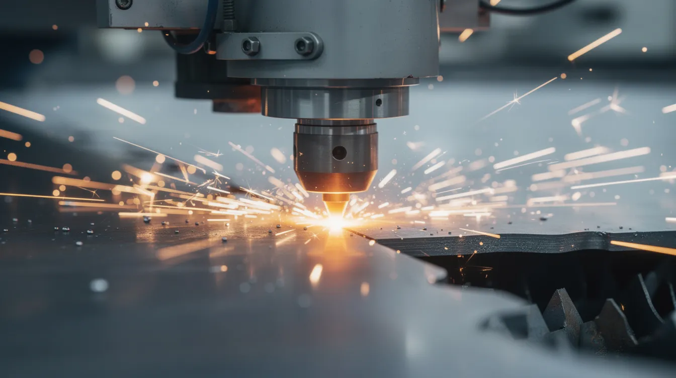
Here are the primary processes we employ and their ideal use cases:
-
Fiber laser cutting – best for intricate 2D profiles, small holes, and tight tolerances on thin sheets up to about 20–25 mm steel. Laser cutting can achieve precision of around 0.1 mm, with the best fiber systems reaching ±0.03–0.05 mm on production parts.
-
Plasma cutting – suited for thicker plate and structural parts where edge aesthetics are secondary. Economical above 25 mm.
-
Turret punching – efficient for high volumes of repeated hole patterns and formed features like louvers or lances in thinner sheet metal.
-
Press brake forming – creates accurate bends, flanges, and channels using V-dies, gooseneck punches, and CNC backgauges. Press brakes can apply up to 25 tons of force per meter, making them capable of bending sheet metal across a wide range of thicknesses.
-
Rolling – curves flat sheets into cylinders, cones, or arcs for shells and ducting.
-
Deep drawing – pulls sheet into continuous-wall shapes like battery cans, motor housings, and sensor shells.
-
Sheet metal stamping – uses a stamping press with progressive or transfer dies for high-volume production of repeatable metal parts.
-
Tapping and threading – adds internal threads to punched or drilled holes.
-
Welding – metal inert gas (MIG) and tungsten inert gas (TIG) processes join sheet metal parts for structural strength.
-
Hardware insertion – PEM self-clinching nuts, studs, and standoffs pressed into sheet for removable assembly.
Incremental sheet forming allows small deformations for complex shapes, and it is increasingly used for prototypes or low-volume parts where dedicated tooling is not justified.
How does Anebon decide which process to use? Consider a bracket needed at 50,000 pieces annually for an automotive customer. At prototype stage, we laser-cut the flat pattern and use press brake forming to bend it-fast turnaround, no tooling investment. Once the design is frozen and volume confirmed, we shift to progressive stamping with a dedicated die set in a punch press, dramatically reducing per-unit cost. Sheet metal fabrication is cost-effective for high-volume production precisely because the right process match drives manufacturing efficiency.
Cutting Technologies: Laser Cutting vs. Plasma Cutting
Laser cutting and plasma cutting are the two dominant sheet metal cutting methods, and each serves a distinct purpose. Understanding when to use which saves both cost and lead time.
A fiber laser focuses a laser beam through a laser cutting head onto the workpiece surface, vaporizing material with extreme precision and a narrow kerf. The heat-affected zone is minimal, which means less distortion and almost no further processing on cut edges. For precision sheet metal parts in electronics, medical devices, and any application with tight features, laser cutting is the clear winner. Anebon’s high-speed laser cutting cells integrate with CAD/CAM software for quick changeovers between prototypes and production runs.
Plasma cutting uses a high-energy ionized gas arc to melt and blow through material. It handles thicker plate efficiently-up to 100 mm or more-where laser systems become impractical or cost-prohibitive. Anebon recommends plasma for heavy industrial machine components, structural frames, and applications where the cut edge will be welded or ground.
Here is how the two compare on key factors:
-
Cut quality and precision: Laser achieves ±0.03–0.05 mm on thin to moderate steel; plasma typically holds ±0.5 mm, with high-definition plasma reaching ~±0.1 mm under 10 mm thickness.
-
Thickness range: Laser is effective up to ~20–25 mm on steel (high-power systems can push beyond); plasma excels on plate above 25 mm and reaches 100 mm or more.
-
Speed: On thin sheets under 6 mm, laser is substantially faster. Above 25 mm, plasma often becomes more cost-efficient per meter of cut.
-
Post-processing: Laser-cut edges are typically clean enough for immediate forming or finishing. Plasma edges often need grinding or deburring.
It is also worth noting that waterjet cutting can cut through metals up to 300 mm thick and leaves no heat-affected zone, making it useful for heat-sensitive base metal alloys or very thick nonferrous metals. However, it is slower and more expensive per part than laser or plasma for most sheet metal work.
Forming and Press Brake Operations
Press brake forming is how flat sheets become three-dimensional parts. A press brake uses a punch and a v shaped die to apply mechanical force along a bend line, creating accurate angles and flanges. Modern CNC press brakes with programmable backgauges allow Anebon to hold bend angle tolerances of ±1.0° for bends under 24 inches, with positioning repeatability that supports multiple bends in sequence without cumulative error.
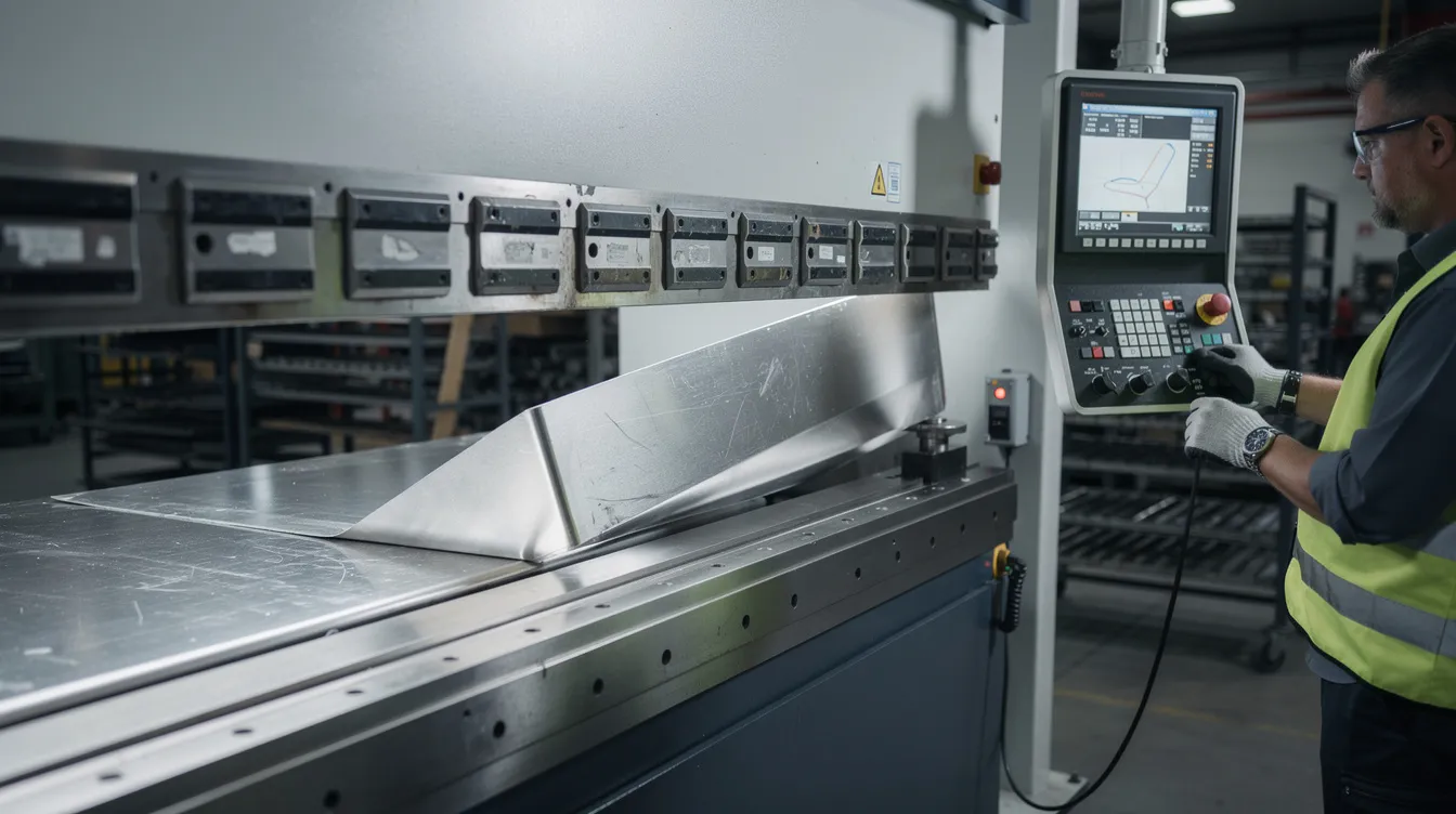
Critical design factors for bending sheet metal include bend radius, K-factor (the ratio of the neutral axis position to material thickness), and bend deduction. Material thickness and grade directly affect the minimum bend radius: mild steel and soft aluminum tempers generally accept an inside radius equal to 1× material thickness, while harder alloys or thicker gauges require larger radii to avoid cracking. Formability is critical for parts requiring complex bending or shapes, so selecting the right temper and alloy early in design prevents costly surprises.
Anebon’s press brake and roll forming capabilities handle bend lengths up to approximately 3 meters in 3 mm steel, with heavier-gauge capacity on shorter lengths. Standard tolerances for sheet metal can vary by machine capabilities, so we confirm achievable tolerances during the DFM review for each project.
Complementary forming processes include hemming (folding an edge over for stiffness or safety), flanging, air bending (where the punch does not bottom out, allowing angle adjustment), and incremental bending for gentle curves. These techniques combine with deep drawing or rolling to produce complex geometries that a single press brake operation cannot achieve.
Design-for-press-brake best practices:
-
Orient bends in the same direction where possible to reduce part handling and setup
-
Keep holes and slots at least 6× material thickness from the bend line (minimum bend edge to hole distance is 6× material thickness)
-
Maintain minimum hole to edge distance of 2× material thickness
-
Use consistent bend radii across the part to minimize tooling changes
-
Specify grain direction if formability is marginal for the chosen alloy
-
Provide relief cuts at internal corners to prevent tearing
Deep Drawing and Complex Shapes
Deep drawing is a specialized forming process that pulls a flat workpiece into a die cavity to create complex shapes with continuous walls. Unlike simple bending or shallow stamping, deep drawing produces parts with significant depth-think battery cans, motor housings, or sensor shells where the height-to-diameter ratio exceeds 1:1. The process is what allows manufacturers to create complex shapes that would be impossible or prohibitively expensive with bending alone.
The key material requirement for deep drawing is ductility. Aluminum alloys like 3003 in O or H14 temper offer excellent elongation (20–28%) and are ideal for decorative or non-load-bearing drawn parts. Alloy 5052 in softer tempers provides higher strength (UTS ~190–230 MPa) with adequate elongation for moderate draws. Low-carbon steel and annealed 304 stainless steel also work, though stainless requires more force and is more prone to springback. The grain direction and more uniform grain structure of the sheet stock directly affect draw quality; material with a uniform grain structure resists tearing and wrinkling better during the forming process.
Tooling for deep drawing-stamp dies, blank holders, draw rings-represents a significant investment. This makes the process most cost-effective at moderate to high production volumes with stable, frozen designs. Cost drivers include draw depth, number of draw steps, material flow control, and defect rates (wrinkling, tearing).
Anebon’s approach to deep drawing starts conservatively. For new designs, we produce soft-tool prototypes using laser cutting and simple forming to validate geometry and fit. Once the design is locked and volume justifies the investment, we manufacture dedicated deep drawing dies. This staged approach lets customers iterate without committing to expensive tooling prematurely.
Material Selection and Material Thickness
Selecting the right sheet metal is crucial for durability and functionality. The choice of metal and material thickness drives cost, weight, formability, and long-term performance. Anebon assists customers during DFM reviews to ensure that material selection aligns with real-world requirements before cutting begins.
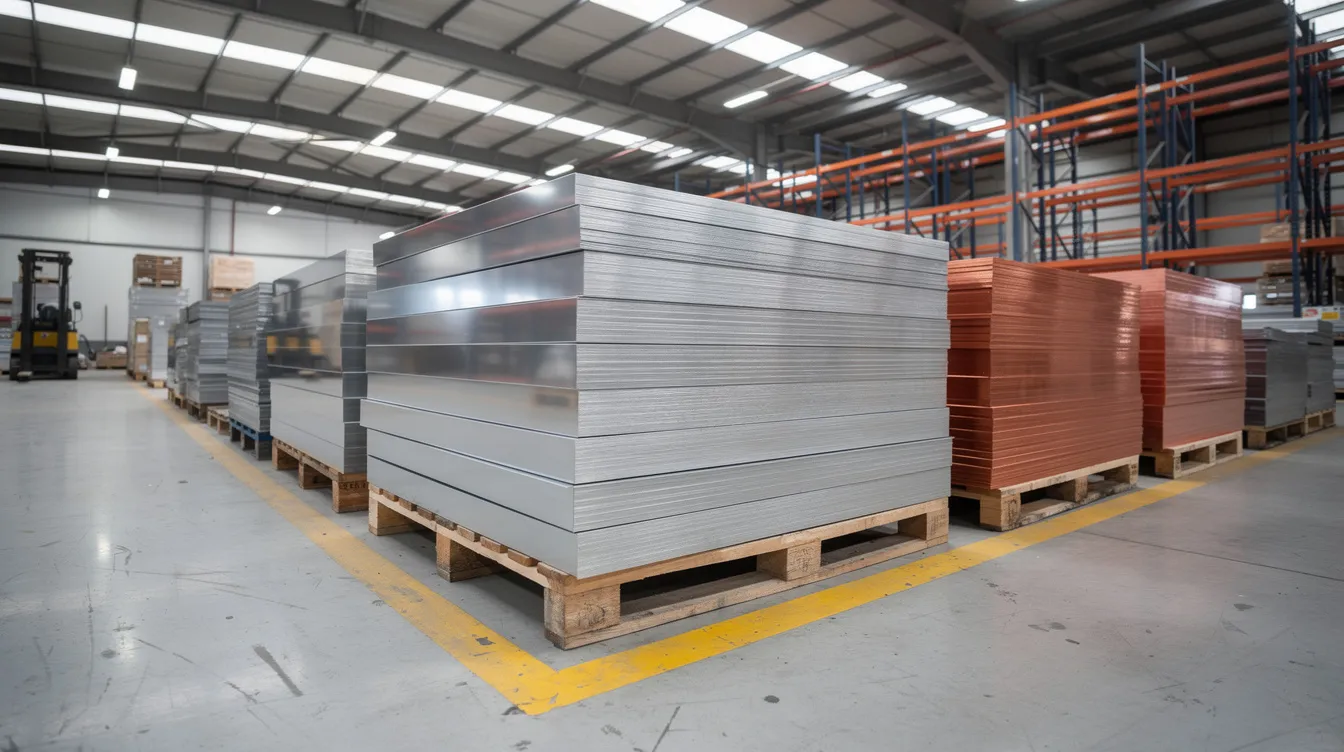
Strength is a key criterion when choosing sheet metal, but it is far from the only one. Engineers must also evaluate corrosion environment, weight targets, electrical conductivity needs, forming complexity, and finishing requirements. Selecting sheet metal requires balancing mechanical properties and environmental resistance-a bracket in a server room faces very different demands than one on a fishing vessel.
Common sheet metals include aluminum, brass, copper, and steel, and each family offers multiple alloys and tempers. Typical sheet metal fabrication materials range from 0.5 mm to 6 mm thick for enclosures and brackets, with heavier structural parts going to 10–12 mm. As material thickness increases, minimum bend radii grow, required press brake tonnage rises, and the cutting process may shift from laser to plasma. Sheet form matters too: specifying coil vs. flat sheets affects flatness, residual stress, and cost.
Regarding gauge vs. metric: the manufacturers standard gauge system is common in the US but ambiguous (steel gauge differs from aluminum gauge). For global supply chain clarity, always specify both gauge and decimal thickness in millimeters on drawings. This prevents misinterpretation between domestic and overseas sheet metal fabricators.
Critical questions to answer before locking material and thickness:
-
What loads (mechanical, thermal, vibrational) will the finished part experience?
-
Is corrosion resistance important for outdoor or harsh environments, and if so, how aggressive is the exposure?
-
What finishes are needed, and do any surfaces require electrical conductivity?
-
What is the weight budget-is this a portable application or a fixed installation?
-
What is the anticipated production volume (prototype, low-volume, or mass)?
Stainless Steel, Steels, and Aluminum Alloys
Stainless Steel (304, 316)
Stainless steel is optimal for high-corrosion environments due to superior resistance. Grades like 304 and 316 are staples in medical, food-processing, and marine applications where hygiene and durability are non-negotiable. Stainless steel provides high corrosion resistance and a sleek finish, making it both functional and aesthetically appealing. It is resistant to corrosion and oxidation even without additional coatings. The trade-off is that stainless is harder to form than mild steel-springback is more pronounced-and cutting stainless requires more laser power or slower feed rates.
Mild Steel and Carbon Steel
Steel is commonly used for structural components in various industries, from automotive frames to industrial machinery panels. Mild steel offers enhanced strength for precise applications and is the most cost-effective option for general brackets, panels, and frames. Mild steel is strong and easy to weld but prone to rust without protective coatings like powder coating or galvanization. Steel is generally easier to weld compared to aluminum, which makes it the default choice for welded assemblies. Hot rolled steel is ideal for structural uses where precision is not critical, while cold-rolled grades (1008/1018) deliver tighter thickness tolerances and better surface finish for fabrication.
Galvanized steel is standard steel coated with zinc to prevent rusting. Galvanized steel resists corrosion and is suitable for outdoor environments, making it a popular choice for weather resistant enclosures, HVAC components, and building cladding.
Aluminum Alloys (3003, 5052, 6061)
Aluminum is corrosion-resistant and ideal for projects where weight is critical. With a density of roughly 2.7 g/cm³ (about one-third of steel), aluminum is lightweight and suitable for portable applications, EV components, and aerospace structures. Alloy 5052 delivers higher strength (UTS ~190–230 MPa) with good formability, while 3003 excels in deep drawing applications due to its superior elongation. Both are compatible with anodizing and chromate conversion coating. Alloy 6061, while stronger, is less forgiving in tight bends and is better suited for CNC-machined features or extrusions than for aggressive sheet forming.
Copper and Brass
Copper is used for high electrical conductivity applications like bus bars, terminals, and RF shields. Copper and brass are used for specialized applications requiring aesthetic or conductive properties. While more expensive than steel or aluminum, copper’s unmatched conductivity makes it essential where current-carrying capacity is the primary design driver. Brass adds machinability and a decorative appearance for architectural or consumer products.
Balancing Performance, Cost, and Fabrication Ease
Every material choice involves trade-offs. Understanding them helps engineers and procurement teams avoid over-specifying (wasting budget) or under-specifying (risking field failures).
Stainless steel vs. painted mild steel is a common comparison. Stainless costs more per kilogram but eliminates the need for painting, masking, and the risk of coating damage exposing the base metal to corrosion. Painted mild steel has a lower raw material cost, but the coating adds 50–80 µm per side, introduces tolerance variation at mating surfaces, and degrades over time in exposed environments. For an indoor electronics chassis, painted steel often wins on cost. For a food-processing panel that sees daily washdowns, stainless is the better long-term investment.
Aluminum vs. steel presents a weight-versus-stiffness decision. Aluminum’s lower density saves weight, but its lower elastic modulus means you may need a thicker cross-section or added stiffeners to match the rigidity of a thinner steel part. For example, a mounting bracket might be 3 mm mild steel with powder coat or 2 mm 5052 aluminum with anodizing. The steel variant is heavier but stiffer per unit thickness and cheaper in raw material. The aluminum version saves roughly 50% in weight and resists corrosion without paint, but costs more per kilogram and requires careful welding technique.
For complex forming-tight bend radii, hems, deep draws-softer, more ductile alloys like 5052-O or 3003 outperform harder grades like 6061-T6, even when the harder alloy is stronger. A design that calls for four tight bends and a partial draw in 6061-T6 risks cracking; switching to 5052-H32 solves the formability problem while still providing adequate strength for many structural applications.
Anebon’s quoting engineers routinely recommend alternative metal alloys or material thicknesses during review. A customer requesting 316 stainless for a mildly corrosive indoor environment might be better served by 5052 aluminum with chromate conversion-saving weight, cost, and forming difficulty without sacrificing function.
Surface Finishes: From Powder Coating to Chromate Conversion
Surface finishes are not purely cosmetic. They determine corrosion resistance, wear life, electrical properties, and whether the final product meets regulatory or aesthetic standards. Sheet metal is essential for building cladding and roofing sheets precisely because proper finishing makes it weather resistant and long-lasting.
Anebon offers a range of finishes for sheet metal parts:
-
Powder coating – a thick, durable, colorful finish ideal for cabinets, panels, and enclosures. Film thickness typically runs 50–80 µm, which must be accounted for in tight clearance areas or on mating surfaces. Cured at ~180–200°C, so not suitable for heat-sensitive assemblies.
-
Wet painting – thinner film, broader color matching capability, multiple coat options, but less durable than powder coat in abrasive environments.
-
Anodizing – electrochemical oxide layer for aluminum alloys, offering corrosion protection, wear resistance, and decorative color. Works well on 5xxx and 6xxx series alloys.
-
Chromate conversion coating (chem film / Alodine) – a thin chemical layer that preserves electrical conductivity while adding mild corrosion protection. Often used under paint or as a standalone finish on EMI gaskets, ground paths, and contact surfaces.
-
Plating (nickel, tin, zinc) – for solderability, conductivity, wear, or corrosion protection on other materials.
-
Brushing and bead blasting – aesthetic textures using abrasive media (including plastic beads for softer finishes). Learn more about surface coating options.
-
Deburring and edge rounding – removing sharp edges for safety, fit, and to prevent coating adhesion failures.
When choosing a finish, consider the operating environment, required lifespan, and any electrical or thermal requirements. Powder coating excels for outdoor and industrial enclosures that need to resist corrosion and look professional. Anodizing is preferable for aluminum alloys in consumer electronics or aerospace where a thin, hard, integrated oxide layer outperforms a bonded coating. Chromate conversion coating is the right call when the part must resist corrosion while maintaining conductivity at mating surfaces-common in RF shielding and grounding applications.
Electrical Conductivity and Finish Selection
Many sheet metal parts serve double duty as structural members and electrical conductors. Enclosures for electronics often need to provide EMI shielding, which requires conductive contact between panels at seams and mounting points.
A fully applied powder coating insulates the surface entirely, which is exactly what you do not want on a grounding boss or a gasket contact area. The solution is selective masking or using conductive finishes on specific zones. Chromate conversion coating preserves conductivity while adding a thin corrosion resistant layer. Tin or nickel plating can also serve this role where solderability or wear resistance matters.
Here is a practical example: an aluminum electronics enclosure requires a professional appearance on the outside and reliable shielding on the inside. Anebon applies chromate conversion coating to all interior surfaces and mounting bosses to maintain ground paths, then powder coats the exterior in the customer’s specified RAL color. Masking drawings from the customer define exactly which areas remain conductive.
Anebon follows customer-specific masking instructions to ensure contact pads, mounting bosses, and bonding areas remain conductive while the rest of the part receives its desired shape and protective finish.
Designing Sheet Metal Parts for Manufacturability
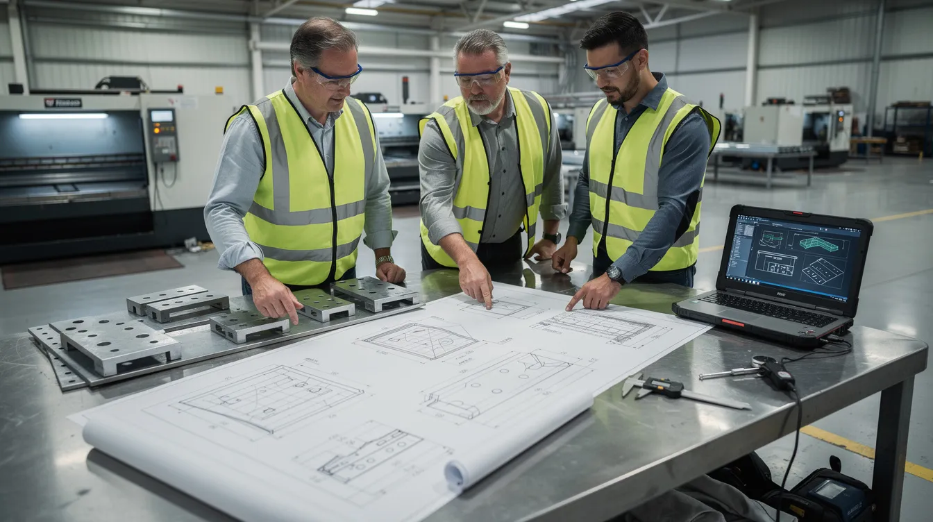
Anebon’s DFM philosophy is straightforward: collaborate with engineers early to catch problems on screen, not on the shop floor. Good design for manufacturability reduces cost, eliminates rework, and shortens lead times. Sheet metal fabrication produces containers for food and chemicals, housings for electronics, bodies for aircraft, and panels for marine vehicles like ships and submarines-all applications where design mistakes are expensive.
Sheet metal is used for aircraft bodies and engine components, making design precision and DFM compliance especially critical in aerospace. Sheet metal can be quickly cut into complex shapes, but only if the design respects the constraints of the cutting process, forming tools, and material properties.
Here are core design rules every engineer should follow:
-
Minimum inside bend radius should be ≥1× material thickness for mild steel and soft aluminum; harder alloys require more
-
Minimum hole-to-edge distance is 2× material thickness to prevent deformation during punching
-
Minimum bend edge to hole distance is 6× material thickness to avoid hole distortion during the forming process
-
Minimum flange length should be ≥4× material thickness for reliable bending
-
Hole diameter should be ≥2× material thickness for clean punching without excessive burr
-
Provide relief cuts at internal corners adjacent to bends to prevent tearing
-
Use consistent bend radii across the part to minimize tooling changes
-
Specify grain direction on the drawing when bends are near the material’s formability limit
For drawing clarity, always include: explicit material grade and temper, thickness in mm, finish specification with coating thickness, critical-to-function dimensions clearly flagged, and a tolerance table referencing ISO 2768 or your internal standard. If the part is geometrically complex, include a flat pattern.
Enclosures, Brackets, and Bus Bars: Practical Examples
Enclosures
A well-designed sheet metal enclosure balances structural rigidity, access for assembly, thermal management, and EMC compliance. Ventilation patterns are efficiently produced by laser cutting, but designers should keep slot widths above 1.5× material thickness to avoid excessive tool wear on punched versions. Access panels need reinforced edges (hems or returned flanges) to resist bowing. For EMI shielding, plan conductive contact paths early-this affects where chromate conversion coating is applied vs. powder coating. Sheet metal is used in marine vehicles like ships and submarines, where enclosure integrity in corrosive, high-vibration environments is paramount.
Brackets
Brackets are the workhorses of sheet metal fabrication. Using bends to form flanges and gussets adds stiffness without increasing material thickness or weight-a 90° flange on a thin bracket can increase rigidity by an order of magnitude compared to a flat strip. When choosing between a fabricated bracket and a CNC-machined one, fabrication wins on cost for thin-wall parts with simple geometry, while machining is better for thick, tight-tolerance features. Corrosion resistance is important for outdoor or harsh environments, so specify galvanized steel or aluminum with appropriate coating for exposed brackets.
Bus Bars
Bus bars carry high currents between components, so material selection centers on electrical conductivity. Copper is the default for high-current applications, but aluminum alloys offer a lighter, cheaper alternative where slightly higher resistance is acceptable. The cross-sectional area must be sized for the current rating, accounting for thermal rise. Maintaining flatness after punching and bending is critical-flattening techniques and stress-relief steps may be needed. Insulation or coating is applied selectively: bus bars often need bare contact surfaces at connection points with corrosion resistant plating elsewhere.
Anebon’s Sheet Metal Fabrication Capabilities
Anebon Metal Products Limited is an ISO 9001:2015 and ISO 14001:2015 certified manufacturer specializing in precision sheet metal, CNC machining, and die casting. Founded in 2010 in Dongguan, China, we serve overseas OEM clients across aerospace, medical devices, automotive, electronics, and industrial machinery.
Our sheet metal fabrication services handle standard metal sheets up to approximately 2500 × 1250 mm, with material thickness ranging from ~0.5 mm to 10–12 mm for most jobs. We work with all common sheet metal fabrication materials: carbon steel, stainless steel, aluminum alloys, copper, brass, and other materials as required by the application. Our CNC laser cutting, press brake, and stamping equipment supports everything from single prototypes to high-volume production.
What distinguishes Anebon is our integrated service model. A single project can combine sheet metal housings with CNC-machined heat sinks or die-cast bases, all moving through cutting, forming, machining, finishing, and assembly within one supply chain. This eliminates coordination between multiple vendors and reduces lead time.
Why global OEMs choose Anebon:
-
Precision tolerances as tight as ±0.002 mm on CNC-machined features and ±0.05 mm on sheet metal operations
-
Rapid prototyping through full scale production with no minimum order quantity restrictions
-
Broad materials range covering ferrous, nonferrous metals, and engineering plastics
-
ISO 9001:2015 and ISO 14001:2015 certified quality and environmental management
-
Responsive DFM feedback and engineering support for overseas design teams
Quality Assurance and Inspection for Sheet Metal Parts
Quality control involves visual, dimensional, and NDT inspections at every stage of production. Anebon’s quality workflow begins with incoming material inspection: we verify thickness, mechanical properties, and surface condition against material certifications before any cutting or forming begins.
During the sheet metal fabrication process, in-process checks monitor cut dimensions, edge quality, bend angles, and formed features against engineering drawings. Dimensional inspection uses tools like callipers and micrometres for standard checks, with coordinate measuring machines (CMMs), height gauges, and go/no-go gauges deployed for tighter-tolerance features. Visual inspection identifies surface imperfections in parts, including scratches, dents, and coating defects against agreed cosmetic standards.
ISO 9001:2015 certification ensures quality management standards are maintained consistently across all jobs. Non-destructive testing detects internal defects without damage when required-particularly relevant for welded assemblies or safety-critical components. For coatings, we perform film thickness checks on powder coat and anodized surfaces, plus adhesion testing (cross-hatch or tape pull) where specified.
Documentation that international customers can expect from Anebon:
-
Material certificates (ASTM, EN, JIS) with traceability
-
RoHS and REACH compliance statements
-
PPAP and FAI (First Article Inspection) reports for automotive and aerospace programs
-
Coating thickness and adhesion test reports
-
Dimensional inspection reports with measurement data for critical features
Sheet Metal Fabrication FAQ
What is the most common sheet metal for fabrication? Mild steel (cold-rolled 1008/1018) is the most widely used due to its low cost, good weldability, and compatibility with powder coating. Aluminum 5052 and stainless steel 304 are the next most common, chosen for weight savings or corrosion resistance respectively.
What thickness of sheet metal is best for enclosures? Most electronic and industrial enclosures use 1.0–2.0 mm sheet for panels and 1.5–3.0 mm for structural frames. The desired shape, required stiffness, and weight constraints determine the final specification. Uniform thickness across an assembly simplifies fabrication and reduces cost.
How tight can tolerances be on sheet metal parts? Laser-cut features can hold ±0.05 mm on production runs. Bend angle tolerance can be ±1.0° for bends under 24 inches. Overall formed-part tolerances depend on part size, complexity, and number of operations.
Is sheet metal fabrication suitable for prototyping? Yes. Laser cutting and press brake forming require no dedicated tooling, making them ideal for prototypes. Anebon can deliver prototype sheet metal parts in days to a few weeks depending on complexity, with the same processes scaling to mass production.
What finishes protect sheet metal from corrosion outdoors? Powder coating, hot-dip galvanizing, anodizing (for aluminum), and chromate conversion coating all provide corrosion protection. The choice depends on material, environment severity, and whether electrical conductivity must be preserved. Sheet metal is strong, durable, and resistant to corrosion when properly finished. Sheet metal is also 100% recyclable, saving energy and supporting sustainability goals in modern manufacturing.
From RFQ to Shipment: How to Work with Anebon
Working with Anebon follows a clear, proven workflow. It starts when you submit an RFQ with your CAD models (STEP, IGES, or SolidWorks files), 2D drawings with GD&T, and specifications for material, finish, and quantity. If you are unsure about any specification, our engineers provide DFM feedback-recommending the right alloy, adjusting bend radii, suggesting alternative manufacturing processes, or flagging tolerance callouts that would drive unnecessary cost.
After quoting, we produce a prototype run for your validation. This prototype uses production-intent processes (not just 3D printing or mockups) so you can verify fit, function, and finish before committing to volume. Once validated, we ramp to production quantities on the agreed schedule, with incoming inspection, in-process monitoring, and final inspection at every step.
For accurate quoting, include the following with your RFQ:
-
Annual volume estimate (or lot size and frequency)
-
Target lead time
-
Material grade, temper, and thickness (specify both gauge and metric)
-
Surface finish requirements including coating type and any masking areas
-
Critical tolerances and any compliance standards (aerospace, medical, automotive)
-
Assembly requirements if Anebon will combine sheet metal with CNC-machined or die-cast components
Anebon supports both rapid prototypes (typically days to a couple of weeks) and long-term supply agreements with scheduled releases. Whether you need a single enclosure prototype or 100,000 precision stamped parts per year, our team is structured to respond quickly and scale reliably.
Ready to get started? Send your drawings and specifications to Anebon for a detailed sheet metal fabrication services quote. Our engineering team reviews every submission personally and responds with DFM feedback, pricing, and lead times-typically within 48 hours for standard projects. We are built to serve overseas OEMs and design teams who demand precision, transparency, and on-time delivery.