Basic knowledge of mechanical drawing | Detailed introduction with pictures and texts
1. Function and content of part drawing
1. The role of part drawings
Any machine is composed of many parts, and to manufacture a machine, the parts must be manufactured first. The part drawing is the basis for manufacturing and inspecting the parts. It puts forward certain requirements for the parts in terms of shape, structure, size, material and technology according to the position and function of the parts in the machine.
2. Contents of parts drawings
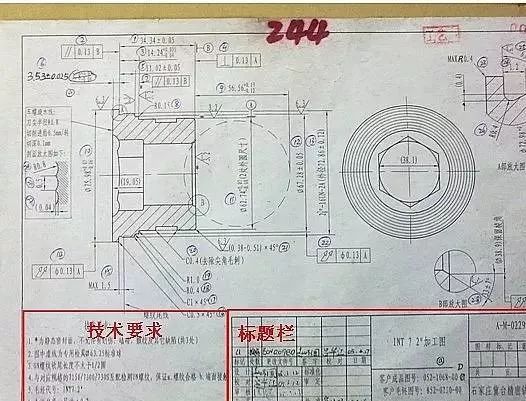
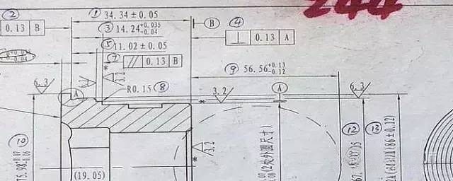
A complete part drawing should include the following contents, as shown in Figure 1:
Figure 1 Parts diagram of INT7 2”
(1) Title column Located in the lower right corner of the drawing, the title column generally fills in the name of the part, material, quantity, proportion of the drawing, the signature of the person responsible for the code and drawing, and the name of the unit. The direction of the title bar should be consistent with the direction of viewing the picture.
(2) A group of graphics used to express the structural shape of the part, which can be expressed by means of view, section view, section, prescribed drawing method and simplified drawing method.
(3) Necessary dimensions reflect the size and mutual positional relationship of each part of the part, and meet the requirements of turning parts manufacturing and inspection.
(4) Technical requirements The surface roughness, dimensional tolerance, shape and position tolerance of the parts, as well as the heat treatment and surface treatment requirements of the material are given.
2. View
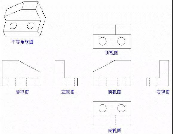
Basic view: the view obtained by projecting the object to the six basic projection surfaces (the object is in the center of the cube, projected to six directions of front, back, left, right, up, down), they are:
Front view (main view), left view, right view, top view, bottom view and rear view.
3. Whole and half dissection
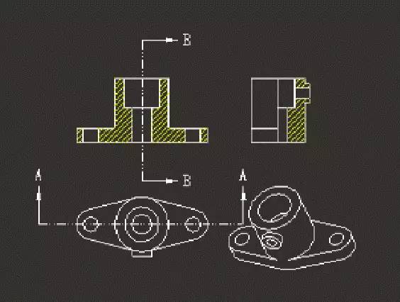
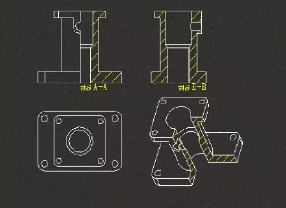
In order to assist in understanding the internal structure and related parameters of the object, it is sometimes necessary to divide the view obtained by cutting the object into a full section view and a half section view.
Full sectional view: The sectional view obtained by completely cutting the object with the sectional plane is called a full sectional view
Half-section view: When the object has a symmetry plane, the figure projected onto the projection surface perpendicular to the symmetry plane can be bounded by the center line, half of which is drawn as a sectional view, and the other half is drawn as a view, called a half-section view.
4. Dimensions and labeling
1. Definition of size: a numerical value representing a linear dimension value in a specific unit
2. Size classification:
1) Basic size The size of the limit size can be calculated by applying the upper and lower deviations.
2) Actual size The size obtained by measurement.
3) Limit size Two extremes allowed by a size, the largest one is called the maximum limit size; the smaller one is called the minimum limit size.
4) Size deviation The algebraic difference obtained by subtracting the basic size from the maximum limit size is called the upper deviation; the algebraic difference obtained by subtracting the basic size from the minimum limit size is called the lower deviation. The upper and lower deviations are collectively referred to as limit deviations, and the deviations can be positive or negative.
5) Dimensional tolerance, referred to as tolerance, is the difference between the maximum limit size minus the minimum limit size, which is the allowable size change. Dimensional tolerances are always positive
For example: Φ20 0.5 -0.31; where Φ20 is the basic size and 0.81 is the tolerance. 0.5 is the upper deviation, -0.31 is the lower deviation. 20.5 and 19.69 are the maximum and minimum limit sizes respectively.
6) Zero line
In a limit and fit diagram, a straight line representing a basic dimension, based on which deviations and tolerances are determined.
7) Standard tolerance
Any tolerance specified in the system of limits and fits. The national standard stipulates that for a certain basic size, there are 20 tolerance levels in the standard tolerance.
Tolerances are divided into three series of standards: CT, IT, and JT. CT series is the casting tolerance standard, IT is the ISO international dimension tolerance, JT is the dimension tolerance of the Ministry of Machinery of China
Different tolerance grades for different products. The higher the grade, the higher the production technology requirements and the higher the cost. For example, the tolerance level of sand casting is generally CT8-CT10, while our company uses international standard CT6-CT9 for precision casting.
8) Basic deviation In the limit and fit system, determine the limit deviation of the tolerance zone relative to the zero line position, generally the deviation close to the zero line. The national standard stipulates that the basic deviation code is represented by Latin letters, the uppercase letter indicates the hole, and the lowercase letter indicates the shaft, and 28 basic deviations are stipulated for each basic size segment of the hole and shaft. Learn UG programming and add Q group. 726236503 to help you.
3. Dimension marking
1) Dimensioning requirements
The size on the part drawing is the basis for processing and inspection when manufacturing cnc milling products. Therefore, in addition to being correct, complete and clear, the dimensions marked on the part drawings should be as reasonable as possible, even if the dimensions noted meet the design requirements and are convenient for processing and measurement.
2) Size reference
Dimensional benchmarks are the benchmarks for marking positioning dimensions. Dimensional benchmarks are generally divided into design benchmarks (used to determine the structural position of parts during design) and process benchmarks (used for positioning, processing and inspection during manufacturing).
The bottom surface, end surface, symmetry plane, axis and circle center of the part can be used as the datum size datum and can be divided into main datum and auxiliary datum. Generally, one design datum is selected as the main datum in each of the three directions of length, width, and height, and they determine the main dimensions of the part. These main dimensions affect the working performance and assembly accuracy of the parts in the machine. Therefore, the main dimensions should be injected directly from the main datum. The rest of the dimensional datums except the main datum are auxiliary datums to facilitate processing and measurement. Secondary datums have dimensions associated with the primary datum.
5. Tolerance and fit
When producing and assembling machines in batches, it is required that a batch of matching parts can meet the design requirements and use requirements as long as they are processed according to the drawings and assembled without selection. This property between parts is called interchangeability. After the parts are interchangeable, the manufacturing and maintenance of parts and components are greatly simplified, the production cycle of the product is shortened, the productivity is improved, and the cost is reduced.
The concept of tolerance and fit
1 tolerance
If the size of the parts to be manufactured and processed is absolutely accurate, it is actually impossible. However, in order to ensure the interchangeability of parts, the allowable dimensional variation determined according to the use requirements of the parts during design is called dimensional tolerance, or tolerance for short. The smaller the value of the tolerance, that is, the smaller the variation range of the allowable error, the more difficult it is to process
2 The concept of shape and position tolerance (referred to as shape and position tolerance)
The surface of the processed part not only has dimensional errors, but also produces shape and position errors. These errors not only reduce the accuracy of cnc machining metal parts, but also affect the performance. Therefore, the national standard stipulates the shape and position tolerance of the surface of the part, referred to as the shape and position tolerance.
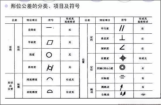
1) Symbols of geometric tolerance feature items
As shown in table 2
2) Note method of dimensional tolerance in drawings of cnc machinery parts
Dimensional tolerances in part drawings are often marked with limit deviation values, as shown in the figure
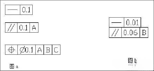
3) The requirements for the shape and position tolerance of the sash are given in the sash, and the sash is composed of two or more grids. The content in the frame shall be filled in the following order from left to right: Tolerance feature symbol, tolerance value, and one or more letters to indicate datum feature or datum system when necessary. As shown in figure a. More than one tolerance feature for the same feature
When required by the project, one sash can be placed under another sash, as shown in Figure b.
4) Measured elements
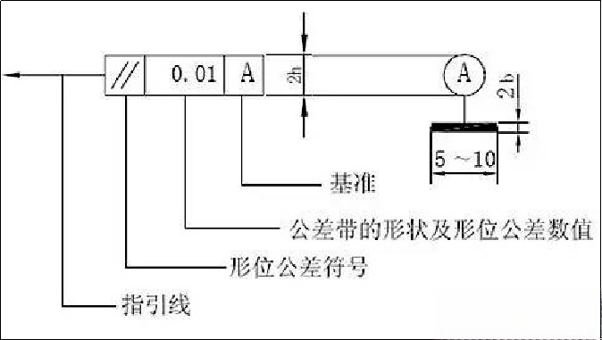
Connect the measured element to one end of the tolerance frame with a guide line with an arrow, and the arrow of the guide line points to the width or diameter of the tolerance zone. The parts indicated by the leading arrows may include:
(1) When the element to be measured is an overall axis or a common central plane, the leader arrow can directly point to the axis or centerline, as shown on the left in the figure below.
(2) When the element to be measured is an axis, the center of a sphere or a central plane, the leader arrow should be aligned with the dimension line of the element, as shown in the figure below.
(3) When the element to be measured is a line or a surface, the arrow of the leading line should point to the contour line of the element or its lead-out line, and should be clearly staggered with the dimension line, as shown on the right of the figure below
5) Datum elements
Connect the datum element with the other end of the tolerance frame with a leader line with a datum symbol, as shown on the left in the figure below.
(1) When the datum feature is a prime line or surface, the datum symbol should be marked close to the outline or lead-out line of the feature, and should be clearly staggered with the dimension line arrow, as shown on the left in the figure below.
(2) When the datum element is an axis, the center of a sphere or a central plane, the datum symbol should be
Align with the feature’s dimension line arrow, as shown in the image below.
(3) When the datum element is the overall axis or common central plane, the datum symbol can be
Mark directly close to the common axis (or common centerline), as shown on the right of the figure below.
3 Detailed Explanation of Geometric Tolerance
Form Tolerance Items and Their Symbols
Form Tolerance Example
| Project | Serial number | Drawing annotation |
Tolerance zone | Description | ||||||||||
| Straightness | 1 |
|
|
The actual ridgeline must be located between two parallel planes with a distance of 0.02mm in the direction indicated by the arrow. | ||||||||||
| 2 |
|
|
The actual ridgeline must be located within a quadrangular prism with a distance of 0.04mm in the horizontal direction and a distance of 0.02mm in the vertical direction | |||||||||||
| 3 |
|
|
The actual axis of Φd must be located in a cylinder whose diameter is Φ0.04mm with the ideal axis as the axis | |||||||||||
| 4 |
|
|
Any prime line on the cylindrical surface must be located in the axial plane and between two parallel straight lines with a distance of 0.02mm. | |||||||||||
| 5 |
|
|
Any element line in the length direction of the surface must be located between two parallel straight lines with a distance of 0.04mm in the axial section within any length of 100mm. | |||||||||||
| Flatness | 6 |
|
|
The actual surface must be located in two parallel planes with a distance of 0.1mm in the direction indicated by the arrow | ||||||||||
| Roundness | 7 |
|
|
In any normal section perpendicular to the axis, its section profile must be located between two concentric circles with a radius difference of 0.02mm | ||||||||||
| Cylindricity | 8 |
|
|
The actual cylindrical surface must be located between two coaxial cylindrical surfaces with a radius difference of 0.05mm |
Orientation Position Tolerance Example 1
| Project | Serial number | Drawing annotation |
Tolerance zone | Description | ||||||||||
| Parallelism | 1 |
|
|
The axis of Φd must be located between two parallel planes with a distance of 0.1mm and parallel to the reference axis in the vertical direction | ||||||||||
| 2 |
|
|
The axis of Φd must be located in a quadrangular prism with a distance of 0.2mm in the horizontal direction and a distance of 0.1mm in the vertical direction and parallel to the reference axis | |||||||||||
| 3 |
|
|
The axis of Φd must be located in a cylindrical surface with a diameter of Φ0.1mm and parallel to the reference axis | |||||||||||
| Verticality | 4 |
|
|
The left end surface must be located between two parallel planes with a distance of 0.05mm and perpendicular to the reference axis | ||||||||||
| 5 |
|
|
The axis of Φd must be located in a cylindrical surface with a diameter of Φ0.05mm and perpendicular to the datum plane | |||||||||||
| 6 |
|
|
The axis of Φd must be located in a quadrangular prism with a section of 0.1mm×0.2mm and perpendicular to the datum plane | |||||||||||
| Inclination | 7 |
|
|
The axis of Φd must be located between two parallel planes with a distance of 0.1mm and a theoretically correct angle of 60° with the reference axis |
Orientation Position Tolerance Example 2
| Project | Serial number | Drawing annotation |
Tolerance zone | Description | ||||||||||
| Concentricity | 1 |
|
|
The axis of Φd must lie in a cylindrical surface with a diameter of Φ0.1mm and coaxial with the common reference axis A-B. The common reference axis is the ideal axis shared by the two actual axes of A and B, which is determined according to the minimum condition. | ||||||||||
| Symmetry | 2 |
|
|
The center plane of the groove must be located between two parallel planes with a distance of 0.1mm and symmetrical arrangement with respect to the reference center plane (0.05mm up and down) | ||||||||||
| Position | 3 |
|
|
The axes of the four Φd holes must be respectively located in four cylindrical surfaces with a diameter of Φt and the ideal position as the axis. 4 holes are a group of holes whose ideal axes form a geometric frame. The position of the geometric frame on the part is determined by the theoretically correct dimensions relative to the datums A, B, and C. | ||||||||||
| Position | 4 |
|
|
The axes of the 4 Φd holes must be respectively located in the 4 cylindrical surfaces with a diameter of Φ0.05mm and the ideal position as the axis. The geometric frame of its 4-hole group can be translated, rotated and tilted up and down, left and right within the tolerance zone (±ΔL1 and ±ΔL2) of its positioning dimensions (L1 and L2). |
Runout Tolerance Example
| Project | Serial number | Drawing annotation |
Tolerance zone | Description | ||||||||||
| Radial circular runout |
1 |
|
|
(In any measurement plane perpendicular to the reference axis, two concentric circles whose radius difference on the reference axis is a tolerance of 0.05mm) When the Φd cylindrical surface rotates around the reference axis without axial movement, the radial runout in any measurement plane (the difference between the maximum and minimum readings measured by the indicator) shall not be greater than 0.05mm |
||||||||||
| End runout | 2 |
|
|
(Cylindrical surface with a width of 0.05mm along the generatrix direction on the measured cylindrical surface at any diameter position coaxial with the datum axis) When the measured part rotates around the reference axis without axial movement, the axial runout at any measurement diameter dr (0<dr<d) on the end face shall not exceed 0.05mm |
||||||||||
| Oblique circular runout |
3 |
|
|
(Conical surface with a width of 0.05 along the direction of the generatrix on any measuring conical surface that is coaxial with the reference axis and whose generatrix is perpendicular to the surface to be measured) When the conical surface rotates around the reference axis without axial movement, the runout on any measuring conical surface shall not exceed 0.05mm |
||||||||||
| Radial full runout |
4 |
|
|
(Two coaxial cylindrical surfaces with a radius difference of 0.05mm and coaxial with the reference axis) The surface of Φd rotates continuously around the reference axis without axial movement, while the indicator moves linearly parallel to the direction of the reference axis. The runout on the entire Φd surface shall not be greater than 0.05mm |
||||||||||
| Full runout | 5 |
|
|
(Two parallel planes perpendicular to the reference axis with a tolerance of 0.03mm) The measured part makes continuous rotation without axial movement around the reference axis, and at the same time, the indicator moves along the direction of the vertical axis of the surface, and the runout on the entire end surface shall not be greater than 0.03mm |
Anebon have the most advanced production equipment, experienced and qualified engineers and workers, recognized quality control systems and a friendly professional sales team pre/after-sales support for China wholesale OEM Plastic ABS/PA/POM CNC Lathe CNC Milling 4 Axis/5 Axis CNC machining parts, CNC turning parts. Currently, Anebon is seeking ahead to even bigger cooperation with abroad customers according to mutual gains. Please experience free of charge to get in touch with us for more specifics.
2022 High quality China CNC and Machining, With a team of experienced and knowledgeable personnel, Anebon’s market covers South America, the USA, the Mid East, and North Africa. Many customers have become friends of Anebon after good cooperation with Anebon. If you have the requirement for any of our products, remember to contact us now. Anebon will look forward to hearing from you soon.
