Aerospace CNC Machining: AS9100 Precision Components Guide
Engineering High-Performance Flight Hardware: A Technical Guide to CNC Machining Services Aerospace Industry Precision Components AS9100
The aerospace sector demands a level of mechanical integrity and dimensional stability that exceeds almost every other industrial application. When sourcing CNC machining services aerospace industry precision components AS9100 compliant, engineers must navigate a landscape where a single micron of deviation or a microscopic material impurity can lead to catastrophic structural failure. This guide analyzes the technical requirements, material science, and Design for Manufacturing (DFM) constraints essential for producing flight-critical hardware.
In the production of aerospace components, the transition from a CAD model to a finished part involves managing extreme thermal loads, tool deflection, and the inherent stresses of high-strength alloys. Whether the project involves structural airframe components in Aluminum 7075-T6 or high-temperature engine parts in Inconel 718, the manufacturing process must be governed by the AS9100 quality management system to ensure full traceability and process repeatability.
Core Concepts & Engineering Principles of Aerospace CNC Machining
Aerospace machining is defined by the intersection of complex geometries and uncompromising material properties. Unlike general commercial machining, aerospace components often require a “Buy-to-Fly” ratio analysis, where the weight of the raw material is significantly higher than the finished part. This necessitates aggressive material removal while maintaining the structural integrity of thin-walled sections.
5-Axis Kinematics and Geometric Complexity
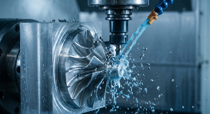
Most aerospace components, such as impellers, turbine blades, and structural ribs, feature non-orthogonal surfaces. Utilizing 5-axis CNC milling centers allows for the machining of complex contours in a single setup. This reduces the “stack-up” error associated with multiple fixtures. In Anebon’s experience, moving a part between three different fixtures can introduce a cumulative tolerance error of up to 0.030mm, whereas a single-setup 5-axis operation can maintain a true position tolerance within 0.005mm.
Tool Pressure and Deflection Management
When machining high-modulus materials like Titanium Ti-6Al-4V, tool pressure becomes a critical variable. The high cutting forces required to shear the material can cause the cutting tool to deflect away from the workpiece. This results in “tapering” on vertical walls. Engineers must account for this by using shorter tool stick-outs and implementing “spring passes”—non-cutting or light-cutting cycles that correct the dimensions after the initial roughing and finishing passes.
Thermal Stability in the Machining Envelope
Thermal expansion is a significant hurdle when holding tolerances of +/- 0.005mm. A 100mm Aluminum 6061-T6 part will expand by approximately 0.023mm for every 10°C increase in temperature. In a high-speed milling environment, the heat generated at the tool-chip interface can quickly migrate into the part. Aerospace-grade CNC facilities must utilize high-pressure flood coolant (often 1000 PSI or higher) and temperature-controlled environments to stabilize the workpiece during the entire machining cycle.
Material Properties & Selection Guide
Selecting the correct alloy for aerospace applications requires a balance between strength-to-weight ratio, corrosion resistance, and machinability. The following table outlines the primary materials used in the aerospace industry and their specific manufacturing characteristics.
|
Material Grade |
Tensile Strength (MPa) |
Machinability Rating |
Primary Aerospace Application |
Thermal Conductivity (W/m-K) |
|---|---|---|---|---|
|
Aluminum 7075-T6 |
572 |
70% (High) |
Wing spars, fuselage structures |
130 |
|
Titanium Ti-6Al-4V |
880 |
20% (Low) |
Engine fasteners, landing gear |
6.7 |
|
Stainless Steel 15-5 PH |
1000+ |
35% (Moderate) |
Actuator components, valves |
17.8 |
|
Inconel 718 |
1035 |
10% (Very Low) |
Turbine blades, exhaust ducting |
11.4 |
|
Aluminum 6061-T6 |
310 |
90% (Excellent) |
Non-structural brackets, housings |
167 |
The Challenge of Superalloys
Inconel 718 and other nickel-based superalloys are notorious for work-hardening. If the cutting tool dwells even for a millisecond without an active chip load, the material surface hardens to a point where it can destroy the carbide insert on the next rotation. Machining these materials requires rigid setups and constant-engagement toolpaths (trochoidal milling) to prevent localized heat buildup.
Aluminum 7075-T6 vs. 2024-T3
While 6061 is the “workhorse” of CNC machining, the aerospace industry relies heavily on 7075-T6 for its superior fatigue strength. However, 7075 is more prone to stress corrosion cracking than 6061. From a machining perspective, 7075 produces shorter, more manageable chips, whereas 2024 can be “gummy,” leading to built-up edge (BUE) on the cutting tool, which degrades surface finish.
Design for Manufacturing (DFM) Best Practices
Designing for the aerospace industry requires a deep understanding of how a cutting tool interacts with the material. Poor DFM leads to increased tool wear, longer cycle times, and higher scrap rates.
1. Internal Radii and Tool Aspect Ratio
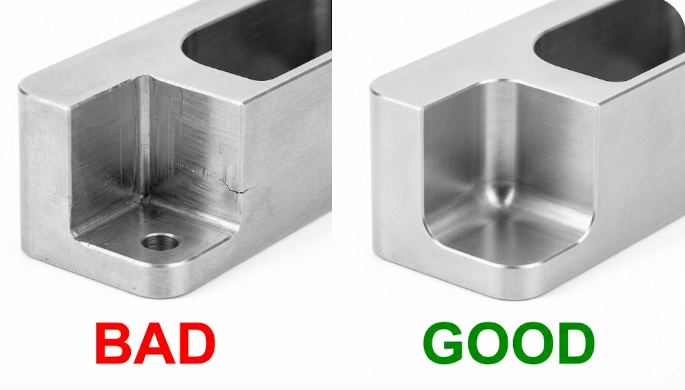
A common error is designing sharp 90-degree internal corners. CNC milling uses rotating round tools; therefore, an internal corner must have a radius.
-
The Rule: The internal corner radius should be at least 10% larger than the radius of the tool used to machine it. For example, if using a 10mm end mill (5mm radius), the design radius should be 5.5mm. This prevents the tool from “burying” itself in the corner, which causes chatter and tool breakage.
-
Aspect Ratio: Avoid deep pockets where the depth-to-width ratio exceeds 4:1. Deep pockets require long tools that are prone to vibration and deflection-induced dimensional errors.
2. Minimum Wall Thickness
Weight reduction is paramount in aerospace, leading to designs with incredibly thin walls.
-
Aluminum: Minimum wall thickness should generally be kept above 0.5mm. Walls thinner than this are prone to “oil-canning” (warping) during machining due to the release of internal material stresses.
-
Titanium: Due to its lower thermal conductivity and higher strength, walls can sometimes be taken down to 0.3mm, but this requires specialized “step-down” machining techniques where both sides of the wall are supported during the cut.
3. Thread Depth and Hole Design
In aerospace fasteners, thread engagement beyond 2x the diameter provides negligible increases in strength but significantly increases the risk of tap breakage. For a M5 bolt, a thread depth of 10mm is usually sufficient. Additionally, avoid blind holes with threads that go all the way to the bottom; always allow for a “chip clearance” space of at least 1.5x the pitch at the bottom of the hole.
Pros, Cons, and Limitations of CNC Machining in Aerospace
While CNC machining is the gold standard for aerospace precision, it is not without its drawbacks. An objective engineering analysis must consider these limitations.
Advantages
-
Material Integrity: Unlike 3D printing (Additive Manufacturing), CNC machining works with wrought billets. This ensures the grain structure of the metal is consistent, providing predictable fatigue life—a non-negotiable requirement for flight-critical parts.
-
Surface Finish: CNC machining can achieve surface roughness (Ra) values of 0.8 microns or better without secondary operations. This is critical for sealing surfaces in hydraulic aerospace components.
-
Scalability: Once a process is validated under AS9100, CNC machining offers high repeatability for batches ranging from 10 to 1,000 units.
Limitations and Drawbacks
-
Material Waste: For complex aerospace brackets, it is common to machine away 90% of the raw material. This “Buy-to-Fly” ratio makes the process expensive, especially when using Titanium or Inconel, so accurately calculating CNC machining cost becomes critical at the quoting stage.
-
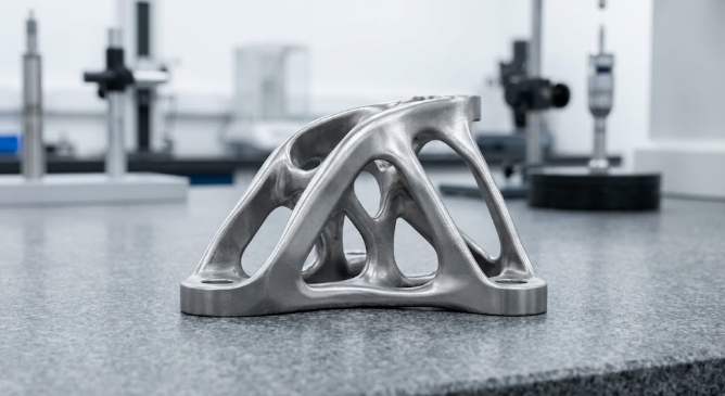
Line-of-Sight Constraint: CNC is a subtractive process. If a tool cannot physically reach a feature (e.g., a curved internal cooling channel), it cannot be machined. This often necessitates complex multi-part assemblies where a single additive part might have sufficed.
-
Residual Stress: Aggressive roughing can introduce residual stresses into the part, causing it to “potato chip” or warp after it is released from the fixtures. Anebon mitigates this by using stress-relief heat treatments between roughing and finishing operations.
Cost Drivers & Budget Optimization
Understanding the cost structure of aerospace machining allows procurement managers to make informed decisions. Aerospace parts are significantly more expensive than commercial parts due to the certification, inspection, and material costs involved.
|
Cost Driver |
Impact on Final Price |
Mitigation Strategy |
|---|---|---|
|
Material Choice |
High (Ti-6Al-4V is 10x the cost of Al 6061) |
Use Aluminum and optimized sheet metal thickness selection for non-structural prototypes. |
|
Tolerances |
Exponential (Tightening from +/- 0.1 to +/- 0.005 can triple cost) |
Only apply tight tolerances to critical mating surfaces. |
|
Setup Time |
High for low-volume runs |
Design parts to be machined in as few setups as possible. |
|
Inspection/Documentation |
Moderate to High (FAI, Material Certs, CoC) |
Consolidate orders to spread documentation costs. |
|
Tool Wear |
High for Superalloys |
Optimize toolpaths to maximize tool life. |
In Anebon’s manufacturing experience, the most effective way to reduce cost is to relax tolerances on non-critical dimensions. A bracket does not need a +/- 0.01mm tolerance on its outer profile if that profile does not mate with another component.
Industry Standards & Tolerances (AS9100 & ISO)
Aerospace machining is governed by strict international standards. AS9100 Rev D is the industry-specific extension of ISO 9001, adding requirements for risk management, configuration management, and “counterfeit part” prevention.
|
Standard |
Focus Area |
Requirement for Aerospace |
|---|---|---|
|
AS9100 Rev D |
Quality Management |
Full traceability from raw melt to finished part. |
|
ISO 2768-m |
General Tolerances |
Used for non-specified linear and angular dimensions. |
|
ASME Y14.5 |
GD&T |
The standard for defining geometric tolerances (Flatness, Parallelism). |
|
IT6 – IT7 |
Precision Fit |
Standard tolerance grades for aerospace bores and shafts and critical bearing and shaft fits. |
Geometric Dimensioning and Tolerancing (GD&T)
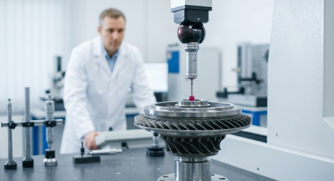
Aerospace drawings rarely rely on simple +/- linear tolerances. Instead, they use GD&T to define the relationship between features. For example, a “Position” tolerance of 0.05mm at “Maximum Material Condition” (MMC) allows for more manufacturing flexibility than a coordinate tolerance, while still ensuring the part will assemble correctly.
Real-World Applications by Industry
The application of CNC machining services aerospace industry precision components AS9100 extends across several sub-sectors:
-
Commercial Aviation: Machining of seat tracks, wing ribs, and fuselage frames. These parts require high-speed milling of large Aluminum 7050 or 7075 plates.
-
Defense & UAVs: Production of sensor housings and gimbal components. These often require electromagnetic interference (EMI) shielding, achieved through precise machining and specialized plating or aluminum surface treatments such as anodizing (e.g., Electroless Nickel).
-
Space Exploration: Components for launch vehicles and satellites. These parts must withstand extreme vibration and thermal cycling. Materials like Beryllium-Copper or Grade 5 Titanium are common.
-
Propulsion Systems: Turbine disks, fuel injectors, and manifolds. These are the most challenging components, often requiring 5-axis simultaneous milling and EDM (Electrical Discharge Machining) for intricate internal features.
Extensive FAQs
Q1: Why is Titanium Ti-6Al-4V so difficult to machine compared to Stainless Steel? A1: Titanium has very low thermal conductivity. While steel conducts heat away through the chips, Titanium retains heat at the cutting edge. This leads to rapid tool breakdown. Furthermore, Titanium’s relatively low elastic modulus makes it “springy,” meaning it tends to deflect away from the tool more than steel.
Q2: What is the significance of AS9100 certification for a CNC shop? A2: AS9100 requires a shop to have a robust system for tracking material heat lots, maintaining calibration records for all measuring tools, and performing root-cause analysis on any non-conforming parts. For an aerospace engineer, this provides the “paper trail” necessary for flight certification.
Q3: Can CNC machining achieve the surface finish required for hydraulic seals? A3: Yes. By using specialized diamond-tipped tooling or high-speed finishing passes with carbide ball-nose end mills, CNC machines can achieve finishes as smooth as 0.4 Ra. In Anebon’s experience, subsequent processes like roller burnishing or honing are sometimes used for even tighter requirements.
Q4: How does “Stress Relieving” affect the machining process? A4: When you remove a large volume of material from a billet, the internal stresses from the original rolling or forging process are unbalanced. This causes the part to warp. Stress relieving (heating the part to a specific temperature for a set duration) after rough machining “settles” the material, allowing the final finishing passes to be accurate.
Q5: What is the standard tolerance for an aerospace-grade CNC turned part? A5: For CNC turning (lathe work), tolerances of +/- 0.005mm on diameters are achievable. However, maintaining this across a long production run requires active thermal compensation on the machine, tight concentricity and runout control, and frequent tool offset adjustments.
Conclusion & Next Steps
The production of aerospace components is a discipline of managing constraints. Success requires a synergy between advanced 5-axis CNC technology, rigorous AS9100 quality protocols, and a deep understanding of material metallurgy. By adhering to DFM principles—such as optimizing internal radii and managing wall thicknesses—engineers can significantly reduce the cost and lead time of flight-critical hardware without compromising safety.
For technical consultation on your next aerospace project or to evaluate the manufacturability of your CAD designs, contact our engineering team.
Upload your CAD files (STEP, IGES, or Parasolid) to info@anebon.com for a comprehensive DFM feedback report and technical quote.