Achieving the Best Milling Finish: Techniques and Tips for Success
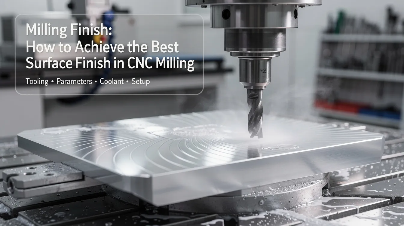
Milling Finish: How to Achieve the Best Surface Finish in CNC Milling
Introduction: What “Milling Finish” Really Means for Your Machined Part
A milling finish refers to the surface texture left on a machined part after a cnc milling operation. The finish is defined by microscopic irregularities and tool marks-peaks, valleys, and patterns created as cutting edges sweep across the material. Surface roughness is typically measured by Ra value (arithmetic average roughness), and a smoother surface has a lower Ra value.
Why does milling surface finish matter? It directly affects sealing performance on gasket and o-ring faces, wear resistance for moving parts, assembly fit between mating components, and the visual surface quality of OEM housings, brackets, and medical fixtures. Standard milling processes typically yield a roughness average of 3.2 µm to 6.3 µm. Smooth machining can improve finish to around Ra 1.6 µm on optimized setups. Pushing below Ra 0.4 µm usually requires other machining methods like grinding, which can achieve finer finishes than milling.
This article covers cutting tools (end mills, face mills, ball nose cutters), milling direction (climb milling vs conventional milling), feeds and speeds, and practical techniques for achieving the best surface finish on your parts. Milling finishes range from rough machined surfaces to polished options, and knowing what drives each outcome puts you in control.
At Anebon Metal Products Limited, we have supported overseas OEMs with precision cnc machining since 2010, delivering consistent milling finish results across aluminum, stainless steel, titanium, and engineering plastics from our ISO 9001:2015 and ISO 14001:2015 certified facility in Dongguan, China.
How Milling Generates Surface Finish: Axial, Radial, and Sculptured Surfaces
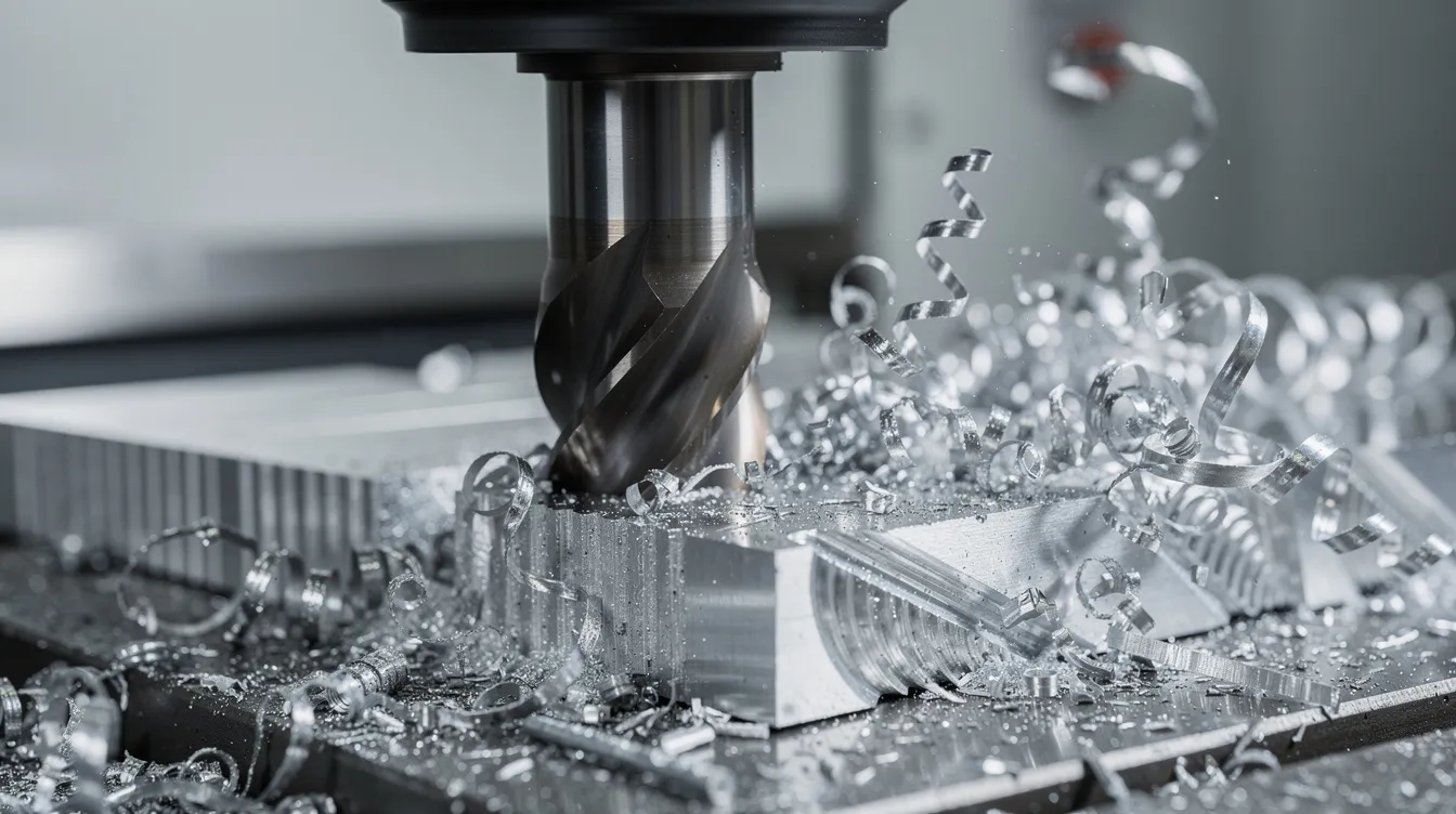
Every milling surface carries a signature left by the cutting process. Understanding whether that signature is axial, radial, or sculptured helps you pick the right machining strategies to meet your Ra or Rz target.
Axially generated surfaces are created by the bottom face of a face mill, shell mill, or end mill. When the tool sweeps across a flat surface, the corner radius and feed per revolution determine the spacing and height of cusps left behind. A larger corner radius produces shallower cusps and a finer finish. Face milling creates flat surfaces with medium finish quality when parameters are properly set.
Radially generated surfaces come from the side-cutting edges of shoulder mills or end mills machining vertical walls, pockets, or profiles. Here, cusp spacing equals feed per tooth, and the radial width of cut (step-over) controls how deeply visible tool marks are left on the wall. End milling is versatile for pockets, slots, and contours, and its flexibility makes it a go-to for 2.5D features.
Sculptured surfaces are 3D contours machined with ball nose or corner radius end mills. Scallop height between adjacent tool paths depends on stepover and tool radius, following the approximation h ≈ s² / (8R). Knowing which surface type dominates your part lets you choose between face milling, side milling, and 3D toolpaths to hit the right specification.
Key Milling Tools and Geometries That Control Surface Finish
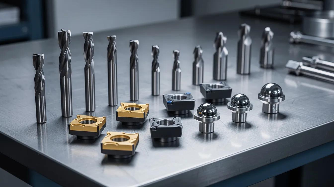
Milling finish quality is influenced by tooling choice more than most engineers initially expect. Different cutting tools-solid carbide end mills, indexable face mills, ball nose cutters-each imprint distinct tool marks and surface textures. The cutter geometry, including corner radius, wiper lands, and rake angle, controls cusp height and the consistency of the resulting finish.
At Anebon, we use different tools for roughing and finishing operations. Roughing tools remove material aggressively; finishing tools are reserved to protect edge sharpness on critical features. Dull tools result in rougher milled surfaces, so maintaining tool sharpness through disciplined tool life tracking is essential. End mills come in various shapes for different finishes, and selecting the best tools for each operation is the foundation of surface finish quality.
End Mills and Corner Radius Cutters
Flat end mills leave sharp edges at corner transitions, which can cause stress risers and burrs. Corner radius (bullnose) end mills replace that sharp corner with a smooth fillet-typically 0.5–1.0 mm radius on a 12.7 mm diameter tool. This small corner radius distributes cutting forces, reduces chipping risk, and leaves a smoother transition on shoulders and pockets.
Use sharp inserts for improved surface finish results, especially during the finish pass. End milling can achieve a finish of 0.29–0.95 µm under optimized conditions with sharp inserts and controlled parameters. When profiling thin walls in aluminum or stainless steel, use the largest end mill whose diameter still fits under the required corner radius-more stiffness means less deflection and better finish.
Face Mills, Shell Mills, and Flycutters
Face mills create flat surfaces perpendicular to the workpiece and are the standard choice for large planar areas. A shell mill functions similarly but mounts on an arbor for rigidity on broader cuts. Face milling tools are larger diameter than end mills, covering more area per pass, and face milling is faster than end milling for material removal on flat surface operations.
Insert height variation among teeth creates steps in the milled surface. Wiper inserts counteract this by “burnishing” between passes. Lead angle matters too-a 45° lead angle reduces axial forces and improves chip formation, while a 90° lead maximizes shoulder accuracy. A fly cutter or single-insert face tool produces extremely fine face finishes on softer materials like aluminum when cycle time is secondary to surface finish quality.
At Anebon, we select between face mills, end mills, and flycutters depending on surface area, required flatness, and the specified Ra/Rz for each face milling operation.
Ball Nose End Mills for Sculptured Surfaces
Ball nose cutters are ideal for smooth, contoured cuts on 3D profiles, mold cavities, and free-form surfaces in aerospace and medical tooling. However, at the tool tip the effective cutting speed approaches zero, which can cause rubbing instead of clean chip formation. Adjusting feed rate and tilting the tool axis helps maintain productive engagement across the active radius.
Stepover percentage directly sets scallop height and the perceived smoothness of a sculptured milling surface. For near-mirror finish on aluminum, stepover may need to drop to 0.02–0.05 mm with a 6–8 mm ball nose tool. Anebon uses 5-axis CNC machining to maintain consistent tool engagement and produce superior finishes on complex shapes across various shapes and geometries.
Special Inserts: Wiper, Round, and High-Positive Geometry
Wiper inserts feature a long parallel land that burnishes the surface during face milling operations, producing very low Ra values even at higher feed rates. They are particularly effective when one insert carries the wiper geometry while the remaining inserts handle primary material removal.
Round inserts (button cutters) have very large corner radii, enabling high feed rates but typically rougher milling finish unless depth of cut and step-over are carefully controlled. High-positive rake inserts generate lower cutting forces, making them suitable for thin-walled parts and softer materials where protecting the surface from deformation matters.
Diamond tools provide exceptional finishes on non-ferrous materials-use diamond tools for the best surface finish on aluminum, copper, and brass alloys where built-up edge would otherwise degrade the result. At Anebon, we select insert style by material group and required finish class, matching the same tool family across prototype and production runs for consistency.
Feeds, Speeds, and Chip Load: Tuning Parameters for the Best Surface Finish
Feed rate and spindle speed directly affect the milling finish more than almost any other factor. The machining process is governed by chip load per tooth-too low and the tool rubs instead of cutting, causing work hardening and poor finish. Too high and you get chatter marks, tool deflection, and visible ridges.
For a 10 mm carbide end mill in aluminum, feed per tooth (fz) of 0.05–0.1 mm/tooth with appropriate cutting speed and sharp cutting edges typically achieves Ra ~1.6 µm. In stainless steel, where material properties promote built-up edge, dropping to fz 0.02–0.05 mm/tooth with flood coolant is often necessary for Ra ~1.6–3.2 µm. Standard milling finishes at default parameters provide a cost-performance balance for engineering applications, but dedicated finishing operations with optimized cutting parameters unlock significantly better results.
At Anebon, we use software-based tool libraries and in-house process sheets to lock in proven finishing parameters for recurring OEM parts, ensuring consistent finish from the first piece to the last.
Setting Feed Rate and Step-Over for Finish Passes
A finish pass typically runs at similar spindle speed to roughing but at reduced feed rate and much smaller radial step-over. Use a light cut of 0.003–0.010 inches for finishing, with step-over around 3–8% of cutter diameter for fine side-wall finishes. These lighter cuts produce lower cutting forces, reducing the risk of deflection marks.
Lighter finish passes are especially important in climb milling on flexible parts where even small force spikes can push the workpiece away from the cutter. Anebon validates finish parameters through sample runs and surface roughness measurement, targeting specific Ra values such as 1.6 µm for sealing faces or 0.8 µm for critical sealed assemblies.
Depth of Cut and Tool Engagement
Axial depth of cut (ap) and radial width of cut (ae) each affect force magnitude and surface finish differently. Leaving 0.1–0.3 mm stock per side for a dedicated finish pass is common in precision cnc machining, with the exact allowance depending on material and tool size.
Too shallow an axial cut depth can cause the tool to skate and burnish instead of cutting cleanly, degrading the finish-particularly in harder materials that resist plastic deformation. CAM strategies that maintain consistent tool engagement along the toolpath prevent visible transitions in surface texture between roughing and finishing zones.
Climb Milling vs Conventional Milling: Direction Matters for Finish
Climb milling and conventional milling represent opposite feed direction strategies relative to cutter rotation, and they produce different chip formation patterns and cutting forces. Climb milling generally produces better surface finishes than conventional milling on modern, rigid CNC machining centers. However, the choice isn’t universal-certain geometries and machine conditions still favor conventional approaches.
At Anebon, we primarily use climb milling for finishing but may select conventional milling for thin walls or when feature stability is a concern. Milling direction is as much about chatter and deflection control as about theoretical chip thickness curves.
When to Prefer Climb Milling for Finish
In climb milling, the cutting edge enters at maximum chip thickness and exits at zero. This produces lower friction at entry, cooler cutting, and a smoother milling surface. Climb milling reduces cutting forces and improves chip evacuation, which translates to less heat buildup and cleaner surface finish measured across the part.
On rigid machines with minimal backlash, climb milling also improves tool life, reduces burr formation, and minimizes work hardening in stainless steel and titanium. For example, finishing the side walls of an aluminum electronic enclosure using climb milling can consistently deliver Ra ≤ 1.6 µm. That said, climb milling can excite resonant frequencies in certain setups, causing chatter-so tool performance must be monitored and spindle speed adjusted if harmonics appear.
When Conventional Milling Can Give a Better Finish
Conventional milling can yield better finishes on thin-walled parts, tall unsupported ribs, or legacy equipment with significant backlash. Because the cutting force in conventional milling pushes the workpiece into its support, it helps stabilize flexible parts during machining, sometimes reducing vibration and chatter marks.
When conventional milling is chosen for a finishing method, use sharp inserts for improved surface finish quality, smaller step-over, and carefully controlled feed rate. For instance, finishing a 1.0 mm thick stainless steel flange may require conventional milling in the feed direction that presses the wall against the fixture, preventing it from being pulled into the cutter and producing a finer finish.
Workholding, Machine Rigidity, and Toolholding: Foundations of a Good Milling Finish
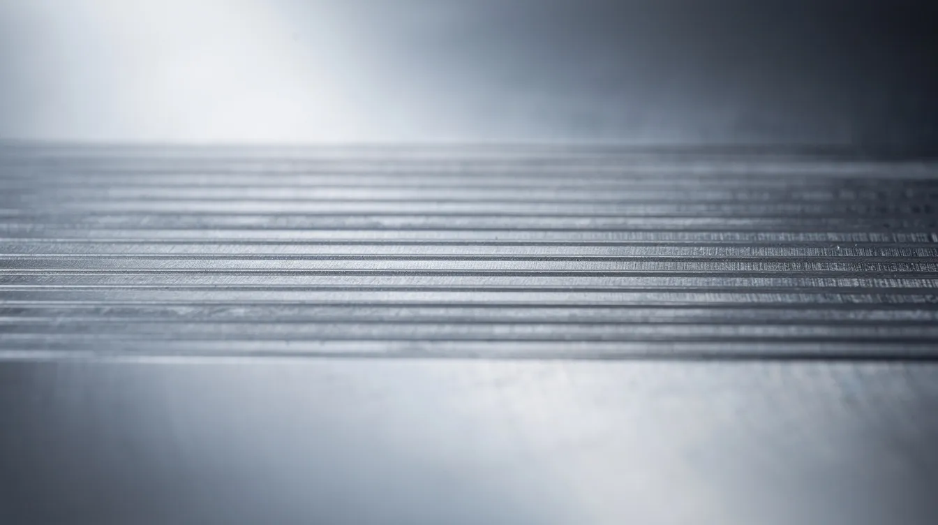
Even with perfect feeds and speeds, a vibrating setup, loose vise, or high-runout toolholder will destroy surface finish. You must minimize vibration and chatter to enhance surface finish quality, and that starts with rigidity in the machine structure, spindle, fixtures, and cutting tools. Toolholders significantly affect rigidity and surface finish quality-a loose or worn holder introduces micro-movement that no parameter adjustment can overcome.
At Anebon, we use high-quality vises, custom fixtures, and balanced toolholders to keep vibration low on long production runs. Basic best practices apply universally: keep tool protrusion short, provide solid support under thin parts, and apply proper torque on clamping bolts.
Fixturing and Workpiece Support
Large contact area between workholding and the part reduces flex, directly improving milling finish on faced surfaces. For thin plates that would otherwise distort or ring, soft jaws, vacuum fixtures, or adhesive fixturing prevent resonance without distorting the workpiece. Excessive clamping force can warp parts, causing waviness even if the toolpath is perfect-torque-limited clamping solves this.
At Anebon, we have finished 3 mm-thick aluminum cover plates using vacuum fixturing to maintain flatness and a consistent finish across the entire surface, eliminating the waviness that conventional clamping would introduce.
Toolholders, Runout, and Balance
Toolholder type matters. ER collet chucks are versatile but can allow more runout than shrink-fit or hydraulic holders. For fine milling finishes, total indicated runout at the tool tip should stay at or below 0.005 mm, especially for small end mills where even slight eccentricity means one tooth cuts deeper than others.
Balanced tooling reduces vibration and enhances surface finish, which becomes critical at higher spindle speed (above ~12,000 rpm) where imbalance generates harmonic chatter. Minimize tool deflection for better surface finish quality by choosing holders with less deflection at the tool tip-shorter gauge length and stiffer construction. Anebon regularly inspects holders and uses balanced assemblies for high-speed finishing of aerospace and electronics components.
Chip Control, Coolant, and Lubrication for High-Quality Milling Finish
Chips trapped between the tool and the milling surface scratch the machined part, creating streaks and raised burrs. Smooth finishes are less likely to trap contaminants, but achieving that smoothness requires getting chips out of the cutting zone before they can cause damage.
Flood coolant, MQL (minimum quantity lubrication), and air blast each play a role in clearing chips and managing heat during finishing operations. The right strategy depends on material properties: aggressive coolant for titanium and stainless, careful chip evacuation in aluminum to avoid recutting swarf. At Anebon, we configure coolant nozzles and air blast specifically for finishing operations on high-visibility surfaces.
Chip Evacuation and Direction of Flow
Direct coolant or air so chips are pushed out of the cut rather than driven back into the toolpath. Horizontal CNC mills often give superior chip evacuation by gravity when finishing pockets and cavities. In gummy materials like pure aluminum or copper alloys, slowing feed rate slightly or adding a spring pass helps prevent chips from welding to the surface.
Programmable coolant nozzles and through-spindle coolant provide consistent chip clearing on deep features where external nozzles cannot reach.
Coolant Choice and Surface Appearance
Water-soluble coolants, cutting oils, and synthetics differ in lubricity and cooling effect, subtly influencing the resulting surface finish. Abrasive particles or contaminated coolant can scratch surfaces; filtration and regular maintenance keep milling finish stable over time across production batches.
Appropriate coolant concentration prevents staining or discoloration on stainless steel and medical-grade alloys. Anebon follows ISO 14001:2015 environmental practices in coolant management while maintaining the dimensional accuracy and finish standards our OEM customers require.
Design & DFM Tips: Specifying and Achieving the Right Milling Finish at Reasonable Cost
Over-specifying a mirror finish on non-critical areas drives cost and lead time without adding functional value. As-machined finishes leave visible tool marks with moderate surface roughness, and as-machined finishes may be suitable for functional parts with no aesthetic requirements. Parts requiring fasteners or sealing faces need low-roughness finishes to prevent leaks, but internal cavities and hidden faces rarely do.
Common callouts include:
-
Ra 6.3 µm – general milled surfaces, non-critical
-
Ra 3.2 µm – standard engineering surfaces
-
Ra 1.6 µm – sealing faces, bearing seats
-
Ra 0.8 µm or below – special applications, may require post processing techniques like polishing or grinding
Anebon provides free DFM feedback on uploaded CAD files, suggesting realistic finish requirements for each surface group based on functional requirements.
Surface Finish Symbols, Units, and Communication
Surface finish refers to measurable texture characteristics specified on drawings using Ra, Rz, root mean square (Rq), and standard grades (N1–N12) per ISO and ASME standards. When specifying, include both the value and process limits where relevant-for example, “Ra ≤ 1.6 µm after CNC milling, no polishing.”
Notes for direction of lay on sealing surfaces or bearing seats ensure proper performance. Anebon confirms measurement method (contact profilometer or optical) with clients for critical surfaces before production, following established surface roughness selection practices.
Balancing Tolerances, Milling Finish, and Cost
Tight dimensional accuracy requirements combined with very finer surface finish specifications multiply cycle time and tooling cost. Softer materials typically yield smoother milling finishes than harder materials under the same tool and parameters-aluminum is inherently more cooperative than hardened steel.
For different materials and applications, consider these post processing techniques:
-
Polished finishes reduce friction critical for rotating or sliding parts
-
Anodizing adds a protective oxide layer to metals like aluminum or titanium and significantly increases wear and corrosion resistance
-
Bead blasting creates a uniform, matte surface texture for cosmetic consistency
-
Powder coating provides superior impact resistance and durability for exterior components
Relaxing a non-critical surface from Ra 0.8 µm to 3.2 µm can eliminate secondary polishing, reducing part cost by 20–30%. A smoother finish improves wear resistance for moving parts, but applying that standard everywhere wastes money. Consult your manufacturing partner early to co-optimize tolerances and finishes-faster wear on tooling from unnecessarily fine finishes across all surfaces adds up quickly on OEM production volumes.
How Anebon Achieves Consistent Milling Finish in Production
Anebon controls milling finish from prototype through mass production using process capability studies (Cp/Cpk) on surface roughness for repeat orders in automotive, electronics, and medical applications. Our in-house measurement equipment-contact profilometers, microscopes, and calibrated gauges-verifies Ra and Rz on every batch.
Our ISO 9001:2015 quality system ties CAM programs, tooling libraries, and inspection data together for traceable surface-finish control. When tool selection and machining strategies are documented and repeatable, consistent finish follows naturally across thousands of parts and multiple material groups.
Example: Improving Face-Milled Finish on an Aluminum Enclosure
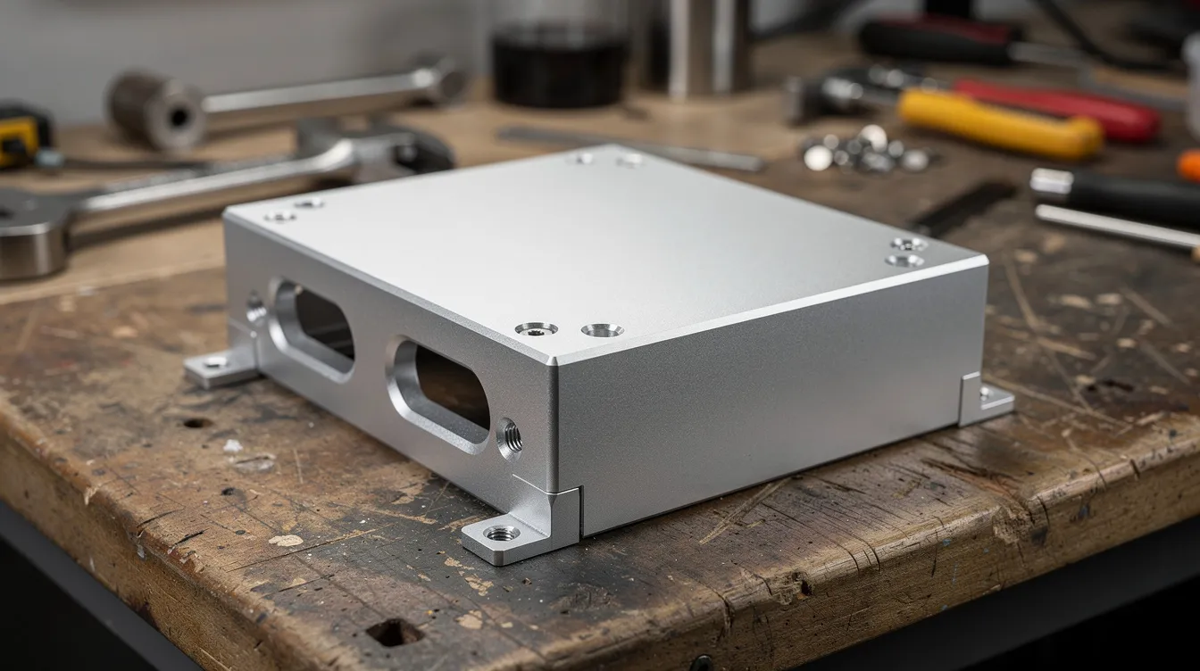
An overseas OEM required Ra ≤ 1.6 µm on the top flat surface of an aluminum electronics housing. Initial machining with a standard face mill at 65% step-over and general-purpose inserts produced Ra ≈ 2.5 µm with visible step marks from peripheral milling overlap.
Process changes included:
-
Switching to a 45° face mill with a wiper insert
-
Reducing step-over to ~60–70% of the wiper width
-
Adjusting feed rate downward for the finish pass
-
Repositioning coolant nozzles to clear chips from the feed direction
The result: consistent Ra around 1.0–1.2 µm across the entire surface, eliminated hand polishing, and 20–30% shorter finishing time across a 1,000-piece batch. The same tool setup was documented in our tool library for future orders-no re-optimization needed.
Next Steps: Getting Help with Milling Finish for Your CNC Machined Parts
Achieving the best milling finish involves correct tool selection, milling direction, feeds and speeds, rigidity, and chip control working together as a system. No single parameter change delivers a finer surface finish in isolation-it’s the combination that counts.
-
Share your CAD files and surface finish specifications with Anebon for review and DFM feedback
-
Leverage our experience from rapid prototyping through full-scale OEM production with consistent milling finish across batches and different materials
-
Get recommended Ra/Rz values included in your quote response, matched to each surface’s functional requirements
Whether you need a smooth finish on a sealing face or a cost-effective as-machined texture on a structural bracket, Anebon’s engineering team can help you hit the right balance. Request a no obligation quote today and let us show you what consistent, production-ready milling finish looks like.