A Comprehensive Guide to the Sheet Metal Manufacturing Industry
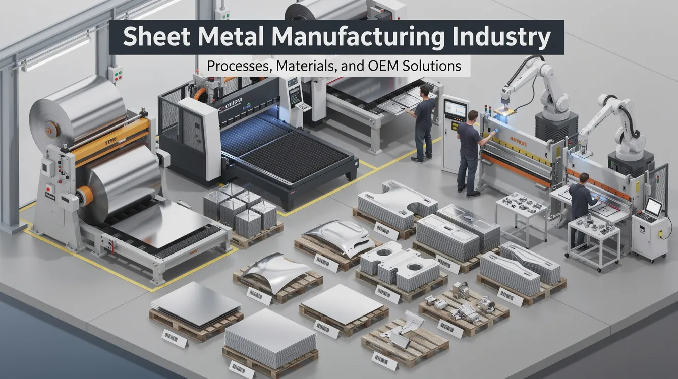
Sheet Metal Manufacturing Industry: Processes, Materials, and OEM Solutions
The sheet metal manufacturing industry transforms flat metal sheets into precise parts that power nearly every sector of the modern economy. From the server racks cooling your cloud infrastructure to the battery trays protecting EV powertrains, sheet metal components are found in various industries including electronics and aerospace. They are also widely used in HVAC systems, automotive, and construction, making this one of the most versatile and far-reaching manufacturing disciplines in existence.
Understanding how this industry works-from raw material through finished part-gives design engineers and OEM buyers a meaningful edge when specifying parts, controlling costs, and selecting suppliers. This guide breaks down the core manufacturing processes, materials, quality standards, and selection criteria that shape every successful sheet metal project.
Introduction to the Sheet Metal Manufacturing Industry
Sheet metal manufacturing covers the full scope of turning flat sheet stock into functional components: cutting profiles, forming three-dimensional shapes, joining pieces into assemblies, and applying protective or decorative finishes. The resulting parts show up everywhere-EV battery trays that must be lightweight yet rigid, data center racks requiring strength and thermal management, medical equipment housings demanding sterility and surface quality, and HVAC ducting and enclosures that keep buildings comfortable. Sheet metal is also essential for automotive body panels, and aerospace components often utilize lightweight aluminum sheet metal. Food processing equipment commonly uses stainless steel sheet metal, while electrical enclosures and cabinets rely on sheet metal for durability and EMC shielding.
It helps to distinguish two related terms. Sheet metal manufacturing broadly refers to creating and processing flat metal sheet from coil or plate through to a usable blank. Sheet metal fabrication is the downstream work: bending, welding, and assembling those blanks into finished parts. A practical example: a supplier receives steel coil, laser-cuts blanks, bends them on press brakes, spot welds the frame, and powder coats it-delivering a completed server rack enclosure. The manufacturing phase is coil procurement and blanking; fabrication is the bending, welding, and finishing.
Key processes you will encounter throughout this article include laser cutting, bending sheet metal, deep drawing, metal fabrication joining methods, and surface treatments like powder coating and anodizing. Sheet metal fabrication techniques include cutting, punching, bending, stamping, and rolling-each suited to different geometries, volumes, and budgets.
Anebon Metal Products Limited is an ISO 9001:2015 and ISO 14001:2015 certified precision metal fabrication partner based in Dongguan, China. Founded in 2010, Anebon serves overseas OEMs from rapid prototyping through mass production, offering tight tolerances, DFM consulting, and a wide range of finishing capabilities.
How the Sheet Metal Manufacturing Supply Chain Works
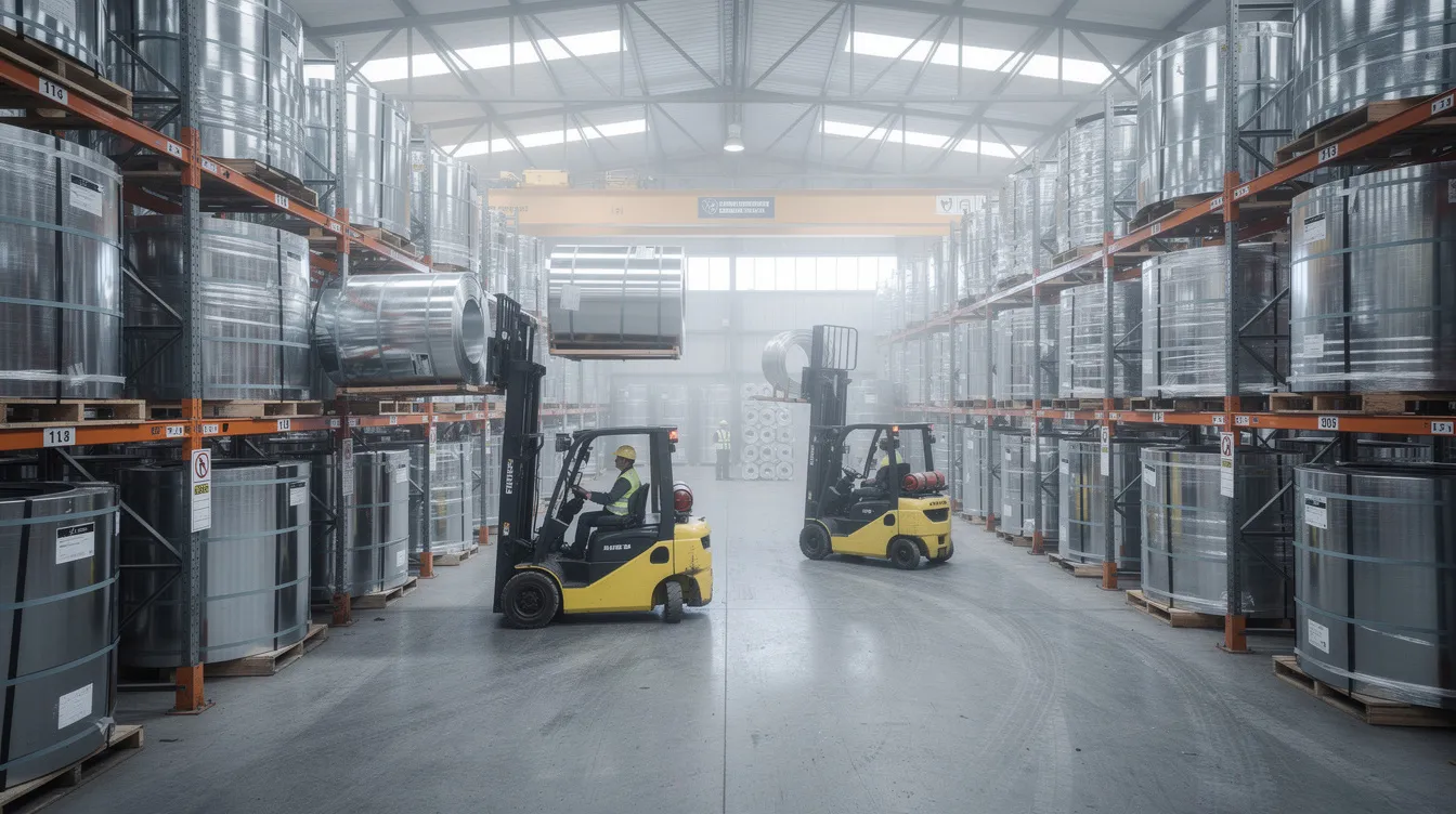
Sheet metal starts life as hot-rolled or cold-rolled coils produced at steel mills and aluminum smelters. These coils are rolled to final gauge, slit to width, flattened, and sometimes pre-treated with galvanizing or pickling. Typical sheet thickness ranges from about 0.5 mm to 6.0 mm; anything significantly above 6 mm is generally classified as plate. Common coil widths in commercial supply chain channels range from roughly 914 mm (36 inches) up to 1,524 mm (60 inches) and beyond, depending on the mill and the material type.
From the mill, raw material flows to service centers that store inventory, shear or slit to order, and distribute to fabrication shops and OEM facilities. This supply chain structure means lead times can vary substantially based on material availability, gauge, and grade-factors that directly influence sheet metal fabrication cost.
Collaboration between OEMs, design engineers, and contract manufacturers is where the fabrication process begins to take shape. OEMs supply engineering drawings-2D prints and 3D CAD models (STEP, Parasolid, SolidWorks native)-specifying material, tolerances, finishes, and critical features. Contract manufacturers respond with digital RFQs, DFM feedback, and tooling plans.
Anebon’s role in this chain is straightforward: engineers receive 3D CAD and 2D drawings from overseas OEM clients, perform in-house DFM reviews to flag issues like holes too close to bends or under-specified tolerances, plan tooling requirements, and manage the full production line from cutting through finishing and packaging.
Core Sheet Metal Processes: Cutting, Forming, Joining, Finishing
Every sheet metal part moves through some combination of four core process groups: cutting, forming, joining, and finishing. Modern sheet metal manufacturing integrates multiple processes on a single part, often in automated cells that support high volume production with minimal handling between steps. Process selection depends on the metallic material being used, sheet thickness, required tolerances, production volume, and target cost. Below, each group is detailed with real industrial context.
Cutting Sheet Metal: Laser Cutting and Beyond
Cutting is the first critical step. It defines the part outline, holes, and slots-and its dimensional accuracy directly influences all downstream bending and joining operations. A poorly cut blank leads to misfit bends and misaligned assemblies.
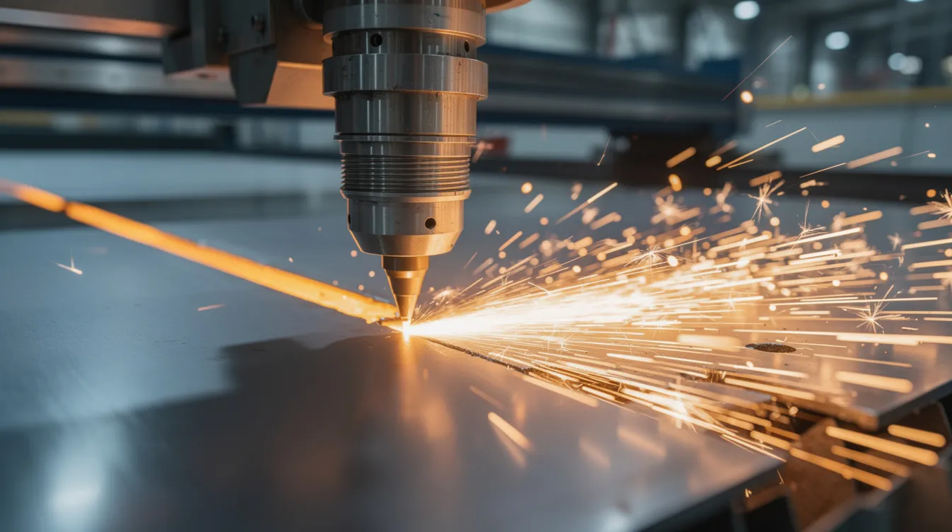
Laser cutting dominates modern sheet metal manufacturing. Fiber lasers, now the industry standard for cutting sheet metal, operate at power levels from about 1 kW to 20 kW depending on material thickness. CNC laser cutting holds tolerances as tight as ±0.1 mm for most features, with ±0.05 mm achievable on small holes under ideal conditions. Laser cutting offers high precision with minimal heat distortion, producing clean edges with minimal burrs. Kerf width on fiber lasers runs approximately 0.15–0.30 mm-narrower than CO₂ lasers, which typically cut at 0.2–0.5 mm kerf.
Cutting techniques in sheet metal fabrication include laser cutting, plasma cutting, and shearing. Each has its place:
-
CNC punching excels at high-speed perforated panels and repetitive hole patterns, often at lower cost per feature than laser for simple shapes.
-
Shearing delivers fast, low-cost straight cuts but with limited precision and rougher edge quality.
-
Waterjet cutting handles thick plates and exotic materials where extreme heat must be avoided, though at slower speeds and higher cost.
-
Plasma cutting suits thicker mild steel and stainless steel where edge quality requirements are moderate.
Anebon uses CNC sheet metal laser cutting linked to CAM software and nesting algorithms. These path optimization algorithms maximize material usage-typically reducing scrap by 5–15%-while shortening lead times for OEM projects.
Forming and Bending Sheet Metal
Forming is how you convert a flat sheet into three-dimensional metal parts without removing material. The primary forming process categories are bending, roll forming, and deep drawing.
Bending sheet metal on CNC press brakes is the most common sheet metal forming operation. Bending uses a punch and a v shaped die to shape sheet metal into the desired shape at a specific bend angle. Key parameters include bend radius, bend allowance (adjusted for the material’s K-factor), and springback-the material’s tendency to partially return toward its original flat patterns after the load is released. Standard angular tolerances are ±0.5° for industrial parts; precision work can achieve ±0.25° or tighter. Designers should specify inside bend radii of at least 1× material thickness for mild steel, and 2–3× for harder alloys like stainless steel or high-strength aluminum. You can learn more about how to bend metal sheet and related bending machines setup in Anebon’s resource library.
Roll forming produces long, continuous profiles of constant cross-section-solar mounting rails, cabinet uprights, structural frames, channel tracks. Line speeds for light-gauge profiles reach 30–60 m/min, making roll forming extremely cost effective for high volume production runs.
Deep drawing forms flat sheets into hollow shapes using a punch that pushes the blank into a die cavity. It is the go-to forming process for components like fuel tanks, kitchen sinks, pressure vessels, and heat exchangers. Single-stage draw ratios reach about 2.0–2.2 for mild steel and 1.8–2.0 for stainless steel. Wall thinning of 10–15% is typical, and wall thickness must be controlled carefully through blank holder force and die radius design. Multi-stage draws with intermediate annealing enable deeper, more complex shapes. Tooling costs are higher than for bending-often only economical at medium to high production volumes. Stamping combines cutting and forming in a single press stroke, and is widely used in sheet metal for automotive panels, brackets, and precision stamping parts.
Joining: Welding and Mechanical Fastening
Joining turns individual sheet metal parts into functional sheet metal assemblies-server rack frames, medical device housings, robotics enclosures, and structural frames for industrial machinery.
Welding techniques in sheet metal joining include TIG and MIG welding, along with resistance spot welding. Welding is the most robust method for joining sheet metal parts when permanent, load-bearing connections are required.
|
Method |
Best For |
Key Considerations |
|---|---|---|
|
MIG welding (GMAW) |
Speed, mild steel, thicker gauges |
Use .023–.030″ wire, pulsed mode to limit heat distortion on thin sheets |
|
Tungsten inert gas / TIG (GTAW) |
Thin stainless, aluminum, visible welds |
Small tungsten electrodes, fast travel, push technique for clean beads |
|
Spot resistance welding |
Automotive panels, high-speed lap joints |
No filler needed; localized heat; less suited for mixed materials |
|
Robotic welding |
Repeatable high-volume weld sequences |
Consistent quality, reduced cycle time, ideal for mass production |
For MIG welding sheet metal, shielding gas composition matters: 75% argon / 25% CO₂ is standard for mild steel, while tri-mix blends suit stainless steel.
Mechanical fastening-screws, bolts, rivets, PEM/self-clinching nuts and studs, and clinching-serves as an alternative or complement to welding. It is preferred when disassembly is needed, when heat distortion must be avoided, or when joining mixed materials. Load capacity requirements, environmental exposure, and cost efficiency all influence the choice between welding and fastening.
Anebon integrates both welding and mechanical fastening in-house, with fixture design and weld sequencing engineered to meet customer load and alignment requirements.
Surface Finishing: From Powder Coat to Anodizing
Surface treatments protect against corrosion, improve appearance, and can add functional properties like electrical conductivity, reflectivity, or wear resistance. For OEM products, visible Class A surfaces have strict cosmetic requirements that must be specified in engineering drawings.
Powder coating is the primary finish for industrial enclosures, brackets, and equipment panels. The process involves pretreatment (cleaning, phosphating, or chemical conversion coating), electrostatic powder application, and oven curing at approximately 180–200°C. Typical film thickness runs 60–120 μm, producing a durable, uniform coating available in virtually any color. Powder coating is RoHS-compliant with low VOC emissions.
Other surface treatments relevant to OEM sheet metal parts include:
-
Anodizing for aluminum: builds a protective oxide layer for corrosion resistance and aesthetic appeal, available in clear or dyed colors.
-
Zinc plating / galvanizing for steel: cost-effective rust prevention for outdoor or humid-environment parts.
-
Chem film / conversion coating for aluminum: enhances paint adhesion and provides moderate corrosion resistance.
-
Bead blasting: uses abrasive particles to create a uniform matte surface texture, often applied before coating.
-
Silk-screen printing: for branding, labels, and indicator markings on the finished part.
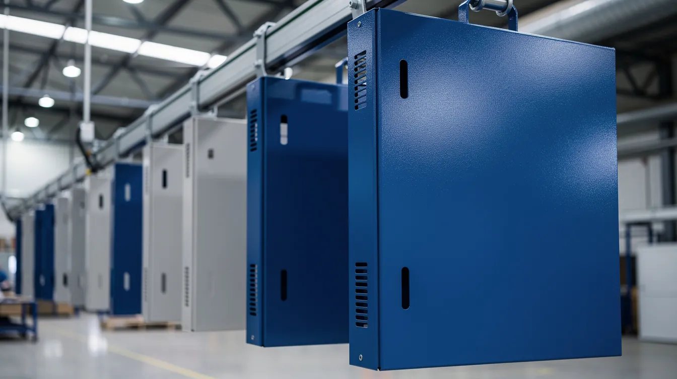
Anebon offers a wide finishing portfolio through certified in-house and partner processes, ensuring cosmetic requirements match engineering drawings and that corrosion resistant specifications are met.
Materials in the Sheet Metal Manufacturing Industry
Choosing the right sheet metal materials is one of the most consequential decisions in any project. It affects formability, weldability, surface treatment options, weight, corrosion resistance, and total metal fabrication cost. Common materials used in sheet metal fabrication include stainless steel and aluminum, but the range extends to copper, brass, titanium, and specialty alloys. Steel is the most common material in sheet metal fabrication by volume.
Material selection also creates fabrication constraints. Aluminum responds differently to bending and welding than stainless steel-it has more springback, lower melting point, and different filler requirements. Copper and brass behave distinctly in deep drawing and laser cutting. These differences mean that sheet metal design must account for the chosen material type from the earliest concept stage.
Anebon can source and certify a wide range of common materials, providing material test certificates (MTCs) and traceability to international standards (ASTM, DIN, ISO) for overseas OEMs.
Common Materials and Their Typical Applications
Here is how the most widely used sheet metal materials compare:
|
Material |
Typical Applications |
Key Properties |
|---|---|---|
|
Mild steel (SPCC, DC01) |
Chassis, brackets, structural frames, cabinets |
Low cost, easy forming/welding, ~400–550 MPa tensile; needs coating for corrosion protection |
|
Galvanized steel |
HVAC enclosures, outdoor cabinets, construction panels |
Zinc coating provides moderate outdoor corrosion resistance at lower cost than stainless |
|
Stainless steel (304, 316) |
Food processing equipment, pharma, medical devices |
Stainless steel is chosen for its corrosion resistance and strength (~515–690 MPa); higher cost, more springback |
|
Aluminum (5052, 6061, 3003) |
Aerospace brackets, EV battery housings, electronics |
Aluminum is lightweight (~2.7 g/cm³ vs steel ~7.85 g/cm³) and corrosion-resistant; 4–5× material cost vs mild steel |
|
Copper / Brass |
Busbars, electrical connectors, decorative panels |
Copper is used for its excellent electrical conductivity; good formability; higher cost |
|
Titanium |
Aerospace structures, medical implant housings |
Titanium is used in high-performance applications due to its strength; limited formability, specialty tooling required |
Material thickness and grade directly affect manufacturability. High-strength steels need larger bend radii on bending machines; soft aluminum grades like 3003 are better suited for deep drawing. Standard tolerances in DFM can vary based on material thickness, so designers must specify gauge alongside dimensional callouts.
Steel and aluminum sheet stock are highly recyclable, supporting circular manufacturing strategies. Anebon’s ISO 14001:2015 certification reflects responsible environmental management in raw material sourcing, wastewater from finishing, and waste handling.
From Engineering Drawings to Production: Fabrication Process Flow
The fabrication process from concept to shipped parts follows a clear sequence:
-
Customer CAD and drawings: 3D models (STEP, Parasolid, SolidWorks) and 2D engineering drawings specifying material, thickness, tolerances, finish, and critical-to-function dimensions.
-
RFQ and DFM review: The manufacturer reviews designs for manufacturability, flagging issues before tooling begins.
-
Rapid prototyping and tooling trials: Low-volume prototypes with soft tooling or simpler jigs validate form, fit, and finish. Rapid tooling allows fast iteration before committing to hard tooling.
-
Mass production: Cutting, forming, joining, and finishing proceed per the validated process. Fully automated machines perform tasks without human operation in many steps, and automatic tool changers reduce setup time to 30 minutes on modern press brakes and laser cells.
-
Inspection, packaging, shipment: Final checks against engineering drawings, documentation (inspection reports, MTCs, PPAPs as needed), and export packaging.
Engineering drawings should explicitly specify material, sheet thickness, tolerances, finishing, and critical-to-function dimensions to avoid ambiguity in the fab shop. Missing or vague specs are the most common cause of quality escapes in overseas production.
Design for Manufacturability (DFM) in Sheet Metal
Design for manufacturability ensures efficient production processes and is where the largest cost savings are unlocked-before a single piece of metal sheet is cut. DFM principles help reduce costs and improve assembly fit by catching design issues early.
High-level DFM guidelines for sheet metal design:
-
Maintain minimum distances between bends and holes: at least 1× material thickness, often 2× for harder materials.
-
Use consistent bend radii across the part to reduce tooling changes.
-
Avoid excessively tight internal corners that concentrate stress and complicate forming.
-
Design around standard fasteners instead of custom brackets where possible.
-
Simplify geometries to reduce the number of forming operations, setups, and welds. A common win: consolidating multiple welded pieces into a single bent profile eliminates weld joints, reduces labor, and improves dimensional accuracy.
Excessive forming can increase costs and complicate manufacturability. DFM reviews ensure parts are manufacturable and cost effective, particularly for overseas production where design change cycles are longer and more expensive.
Anebon’s engineers routinely mark up 3D models and drawings, suggesting improvements tailored to their specific CNC laser cutting, bending, and welding capabilities. Early collaboration on DFM reduces tooling costs, scrap rates, and lead times.
Digital Design, CAD/CAM, and Simulation
CAD platforms generate flat patterns with bend allowances, K-factors, and automatic relief features that directly drive CAM programs for laser cutting and press brakes. This digital thread-from 3D model to flat pattern to machine code-eliminates manual translation errors and accelerates quoting.
For critical parts like deep drawn housings or complex shapes in high-strength alloys, forming and springback simulation (FEA) predicts how the material will behave before any physical tryout. This reduces tooling rework and shortens development timelines significantly.
Current trends in sheet metal manufacturing include digitalization and automation. Smart factories utilize interconnected machinery for efficient metal fabrication processes, linking laser cutters, press brakes, and welding cells into integrated production flows. Anebon’s digital workflow imports native 3D files, creates optimized cutting nests and bending programs, and maintains revision control for OEM customers-resulting in more predictable lead times, higher first-pass yield, and consistent quality from prototype to mass production.
Advantages of Sheet Metal for OEM Product Design
Sheet metal fabrication is known for its high strength-to-weight ratio and design flexibility, making it a preferred route for a wide range of OEM products. The core advantages of sheet metal over alternative manufacturing methods include:
-
Strength-to-weight ratio: sheet metal parts deliver structural performance at lower weight than solid machined or cast components.
-
Scalability: the same processes work from single prototypes to mass production, with cost efficiency improving as volumes rise.
-
Design agility: because production starts from flat sheet stock, design changes are relatively quick. Cutting and bending programs can be updated without fully new molds-unlike injection molding or some casting routes.
-
Finishing versatility: compatibility with powder coating, anodizing, plating, painting, and other surface treatments supports diverse aesthetic and functional requirements.
These advantages of sheet metal connect directly to product categories like electronics enclosures, robotics frames, EV battery cases, aerospace brackets, and cleanroom equipment.
Anebon’s mixed capabilities-cnc machining, die casting, and sheet metal fabrication under one roof-let clients choose the right process or combination for each part in a complex assembly. A single enclosure project might combine laser-cut and bent sheet metal panels with CNC-machined mounting features and die-cast structural brackets, all managed through one supplier. How much does sheet metal fabrication cost compared to alternatives? For medium and large volumes, it is typically the most cost effective path to production-ready metal parts, especially when removing material via machining would waste significant stock.
Quality Assurance and Standards in Sheet Metal Manufacturing
Defects in sheet metal fabrication can arise from inaccuracies in process design, so robust quality assurance is non-negotiable. Typical quality checks in sheet metal manufacturing include:
-
Dimensional inspection: coordinate measuring machines (CMM) for tight tolerances, gauges for bends and hole spacing, optical scanners for flatness.
-
Weld quality inspection: visual checks, dye-penetrant testing, spot weld shear tests for load-bearing joints.
-
Coating thickness measurement: gauges and XRF instruments verify powder coat or plating meets specification.
-
Cosmetic surface checks: inspection under standard lighting for Class A surfaces-looking for dings, scratches, and coating uniformity.
Process controls follow a structured sequence: first-article inspection (FAI) validates setup, in-process checks monitor each batch, and final inspection verifies every dimension and finish callout against engineering drawings and customer specifications.
ISO 9001:2015 provides the framework for quality management, and ISO 14001:2015 covers environmental management. Anebon holds both certifications. For overseas OEMs, documentation practices include PPAPs when required, full inspection reports, material certificates, and traceability from raw sheet to finished part-meeting the rigorous demands of the manufacturing industry.
Robotic operators improve productivity and quality in fabrication by performing repetitive weld and handling tasks with consistent precision. Automated systems enhance safety by reducing human error, particularly in high-speed cutting and press forming operations.
Industry Use Cases and Applications
The breadth of the sheet metal manufacturing industry is best illustrated through specific applications:
Aerospace: Avionics boxes, engine nacelle panels, and structural brackets demand tight tolerances, high strength-to-weight performance, and fatigue resistance. Press forming and cnc machining of aluminum and titanium alloys are standard, with finishing critical for corrosion protection.
Medical devices: Surgical device frames, imaging equipment housings, and instrument trays require hygienic surfaces (often polished stainless steel at 32 μin Ra or better), cleanability, and biocompatible coatings. Combinations of laser cutting, bending, and mechanical fastening meet these standards.
Automotive and EV: Battery enclosures, chassis brackets, and body panels use galvanized steel or aluminum for weight reduction and corrosion resistance. Sheet metal is used in automotive body panels at enormous scale, with stamping and robotic welding enabling high volume production.
Industrial automation and robotics: Machine guards, control panels, and structural frames for industrial machinery need rigidity, dimensional stability, and often EMC shielding. Load capacity and press forming precision are critical.
Electronics and data centers: Server racks, telecom enclosures, and power distribution units demand precise alignment for airflow, powder coating or anodizing for aesthetics, and grounding provisions for EMC compliance.
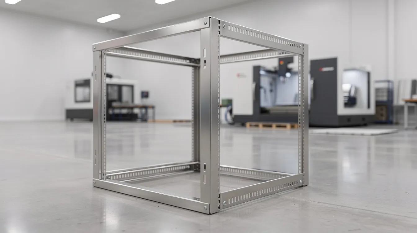
Anebon has experience working with overseas design teams across these applications, supporting both rapid prototypes for R&D validation and stable mass production for mature products. The combination of sheet metal laser cutting, form sheet metal operations, deep drawing, mechanical fastening, and powder coating addresses industry-specific standards from IP ratings to cleanability to structural stiffness.
Selecting a Sheet Metal Manufacturing Partner
Choosing the right sheet metal fabricators is a strategic decision that affects quality, cost, and time-to-market. Key criteria for OEMs and design engineers:
-
Process range: Does the partner cover cutting, forming, machining, and finishing? Integrated capabilities reduce supplier count and simplify project management.
-
Tolerances capability: Can they hold the tight tolerances your design requires-down to ±0.002 mm on CNC-machined features?
-
Materials expertise: Do they source, certify, and have experience forming your chosen sheet metal materials?
-
QA systems and certifications: ISO 9001:2015 and ISO 14001:2015 as baseline; industry-specific certifications (AS9100, PPAP) as needed.
-
Communication and lead times: Responsive engineering support and realistic scheduling, especially across time zones.
The sheet metal manufacturing industry faces skilled labor shortages and supply chain disruptions, and the industry is moving towards reshoring production to mitigate supply chain risks. Partnering with an established, well-certified manufacturer helps insulate your program from these pressures.
Anebon brings over a decade of experience (since 2010), a focus on precision metal fabrication, support for tight tolerances, and a strong track record with overseas clients across aerospace, medical, automotive, electronics, and industrial sectors. Their integrated offering-sheet metal fabrication, cnc machining, and die casting-means fewer vendors to manage and tighter control over quality and delivery.
If you are developing new sheet metal parts or looking to improve cost and quality on existing programs, send your engineering drawings or 3D CAD models to Anebon for a detailed DFM review and quotation. Early collaboration on manufacturability is the single most effective way to reduce cost, compress timelines, and get your product right the first time.